0 - Introduction
For the people looking into a way to display stuff on your Esp32 projects with very little power consumption, there is no better alternative than an E-Ink (E-Paper) display, because this type of display keeps it’s ‘image’ without power, it only needs to be turned on while updating what’s on your screen, making it the king of power efficient displays, another big positive point that E-Ink displays have is readability, they usually have very high contrast (black and white) and very good resolution.
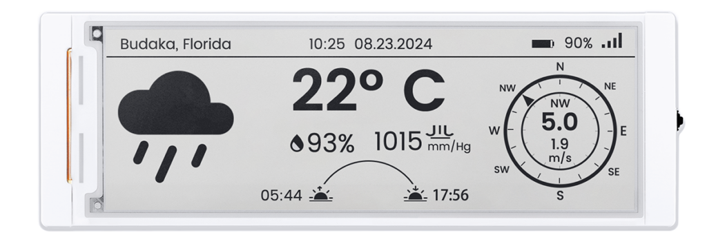
Because of how good E-Ink displays are, in today’s article I introduce you to the new CrowPanel 5.79” E-Paper kit from Elecrow, a compact yet powerful kit designed both for amateurs and professionals. Besides the excelent screen this kit also comes with an Esp32 S3 with 8MBs of Flash and PSRAM.

1 - Specifications
| Spec | Value |
|---|---|
| MCU | Esp32-S3-Wroom-1-N8R8 |
| Flash | 8 MB |
| PSRAM | 8 MB |
| Display Driver | SSD1683 |
| Display Resolution | 792 * 272 Pixels |
| Interfaces | 1x UART, 1x Bat, DuPont header (12x GPIO + 4x 3.3V + 4x Ground), 1x TF Card Slot (MicroSD) |
| Buttons | 1x Dial Switch (Up, Down and In), 1x Menu, 1x Back, 1x Reset, 1x Boot |
| Dev Environments | Arduino IDE, Platform IO, Esp-IDF, Micro Python |
| Refresh Modes | Full, Partial, Fast |
| Operation Temperature | 0~50℃ |
| Storage Temperature | -25~70℃ |
| Display Material | Active Matrix Electroph oretic Display (AM EPD) |
| Size | 5.79'' |
2 - Pins and other IO
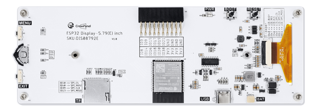
The first time you try to code with the CrowPanel, you might be confused as to which component is attached to which pin. In the following image, that is available on Elecrow’s store page, you can see a label of all of the connections:

But because the images on the store’s page can be a little hard to read, I made a header file with all the usable pins of this kit, if you wish to use these definitions, all you have to do is create a file named ‘crowpanelpins.h’ in your source directory and paste the code below into it:
#ifndef _crowpanelpins_h_
#define _crowpanelpins_h_

#include <Arduino.h>

// Crowpanel Pins
#define IO1_EXIT GPIO_NUM_1
#define IO2_MENU GPIO_NUM_2
#define IO3 GPIO_NUM_3
#define IO4_DOWN GPIO_NUM_4
#define IO5_CONF GPIO_NUM_5
#define IO6_UP GPIO_NUM_6
#define IO7_LCD_3_3_CTL GPIO_NUM_7
#define IO8 GPIO_NUM_8
#define IO9 GPIO_NUM_9
#define IO10_SPI_CS GPIO_NUM_10
#define IO11_SPI_MOSI GPIO_NUM_11
#define IO12_SPI_CLK GPIO_NUM_12
#define IO13_SPI_MISO GPIO_NUM_13
#define IO14 GPIO_NUM_14
#define IO15 GPIO_NUM_15
#define IO16 GPIO_NUM_16
#define IO17 GPIO_NUM_17
#define IO18 GPIO_NUM_18
#define IO19 GPIO_NUM_19
#define IO20 GPIO_NUM_20
#define IO21 GPIO_NUM_21

#define IO38 GPIO_NUM_38
#define IO39_SPI_CLK GPIO_NUM_39
#define IO40_SPI_MOSI GPIO_NUM_40
#define IO41_LED GPIO_NUM_41
#define IO42_TF_3_3_CTL GPIO_NUM_42

#define IO45_CS GPIO_NUM_45
#define IO46_DC GPIO_NUM_46
#define IO47_RES GPIO_NUM_47
#define IO48_BUSY GPIO_NUM_48

// SD Card Pins
#define IO_SD_CS IO10_SPI_CS
#define IO_SD_MOSI IO40_SPI_MOSI
#define IO_SD_CLK IO39_SPI_CLK
#define IO_SD_MISO IO13_SPI_MISO
#define IO_SD_POWER IO42_TF_3_3_CTL

// E-Ink display Pins
#define IO_EPD_BUSY IO48_BUSY
#define IO_EPD_RES IO47_RES
#define IO_EPD_DC IO46_DC
#define IO_EPD_CS IO45_CS
#define IO_EPD_CLK IO12_SPI_CLK
#define IO_EPD_MOSI IO11_SPI_MOSI
#define IO_EPD_POWER IO7_LCD_3_3_CTL
#define IO_EPD_SPI FSPI

// Rotary Switch Pins
#define IO_RSW_UP IO6_UP
#define IO_RSW_DOWN IO4_DOWN
#define IO_RSW_SEL IO5_CONF

// Push switch Pins
#define IO_SW_MENU IO2_MENU
#define IO_SW_EXIT IO1_EXIT

// Power LED
#define IO_LED IO41_LED
#define IO_LED_INIT pinMode(IO_LED, OUTPUT)
#define IO_LED_ON digitalWrite(IO_LED, HIGH)
#define IO_LED_OFF digitalWrite(IO_LED, LOW)

// GPIO Pins
#define IO_GPIO_B1 IO38
#define IO_GPIO_B2 IO20
#define IO_GPIO_B3 IO18
#define IO_GPIO_B4 IO16
#define IO_GPIO_B5 IO14
#define IO_GPIO_B6 IO8

#define IO_GPIO_F1 IO21
#define IO_GPIO_F2 IO19
#define IO_GPIO_F3 IO17
#define IO_GPIO_F4 IO15
#define IO_GPIO_F5 IO9
#define IO_GPIO_F6 IO3

// Not Connected
#define IO_NC GPIO_NUM_NC

#endif
One thing I like to do is to add the code below at the start of the setup function, with it, the power LED turns on almost as soon as the Esp gets power:
void setup()
{
    IO_LED_INIT;
    IO_LED_ON;

    // Your code
}
If you, like me, use VSCode and PlatformIO for Esp coding, you will need this custom ‘platformio.ini’ file:
[env:esp32-s3-devkitc-1]
platform = espressif32
board = esp32-s3-devkitc-1
framework = arduino
board_build.arduino.memory_type = qio_opi
board_build.flash_mode = qio
board_build.psram_type = opi
board_upload.flash_size = 8MB
board_upload.maximum_size = 8388608
board_build.extra_flags =
	-DBOARD_HAS_PSRAM
lib_deps = bblanchon/ArduinoJson@^7.2.0
3 - The Good
Excelent display, excelent micro controller, excelent build quality, it is actually hard to find a reason not to like this kit. The SD card reader for me is one of the best features, with it, you can save a lot more high-res images to display.
Besides what I stated before the other features of this kit that made me love it even more were the battery connector that let’s you connect a coin battery to make a trully wireless display that can display stuff 24/7 for a long time without needing to be changed and the mounts on the back that let you make custom mounts for it.
4 - The Bad
The only ‘problems’ I found with this kit are the need to use a custom Platform IO configuration file, the lack of a backlight, which makes it very hard to read the contents of the display at night or in the dark, and there is only 12 pins empty, besides that there is nothing to complain about with this kit.
Of the 3 ‘problems’ I stated before, the need of a backlight and having only 12 free pins, might not even affect you depending on your use case.
There is also two more things I would categorize as bad, but not bad about the kit but more about E-Ink displays in general, one being the SLOOOW refresh rate, we are talking about 1 to 2 seconds if the whole screen needs to be updated, and the fact that there is only two colors, there are 3 and 4 color E-Ink displays out there but for DIY projects the two color, black and white display is the most common.
5 - Use cases
This kit can be used on retail as a cheap wireless price tag that you can code to automatically update prices every day or after a specified ammount of time. On your home you can also connect the Esp32 on this kit to your Home Assistant server and control your smart home through it, but there are a lot more use cases to it.
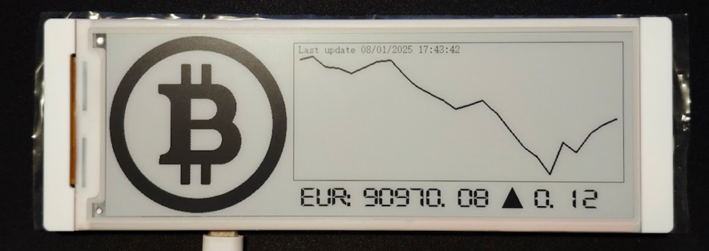
As an example I coded a cryptocurrency ticker that gets the latest price of Bitcoin from CoinGecko and displays it on the screen along with a graph and the difference in percentage:

6 - Should you buy it?
If you need to make anything related to saving power and need a screen with good contrast where you won’t be refreshing it’s contents multiple times a second there is no better alternative than a E-Ink display and with this kit you won’t miss anything, so yes, 100%.
If you like this kit but think it is too big, or you need a different size, Elecrow also offers kits of the following sizes:
- 1.54”, 152 by 152 pixels
- 2.13”, 122 by 250 pixels
- 2.9”, 128 by 296 pixels
- 3.7”, 240 by 416 pixels
- 4.2”, 400 by 300 pixels
- 5.79”, 272 by 792 pixels (the one being reviewed)
Just keep in mind that would also need to change the display library to match your kit, you can get it on any of the examples for your kit size in Elecrow’s Github repo.
And that’s all, thanks for reading and stay tuned for more tech insights and tutorials. Until next time, and keep exploring the world of tech!
