0 - Introduction
With a lot of projects, having a way to display information is vital, so we will, in this article, use one of the most popular libraries there is, with the ammount of oled displays supported, it is unmatched.
That library is U8g2.
In this tutorial I will use a 128×32 oled display with the SSD1306 chip, but you can adapt it to many more displays, by just changing the variable type of ‘oled’ in the code.
If you don’t have an Esp32, you can get one here and you can also get the display here.
1 - Install Library
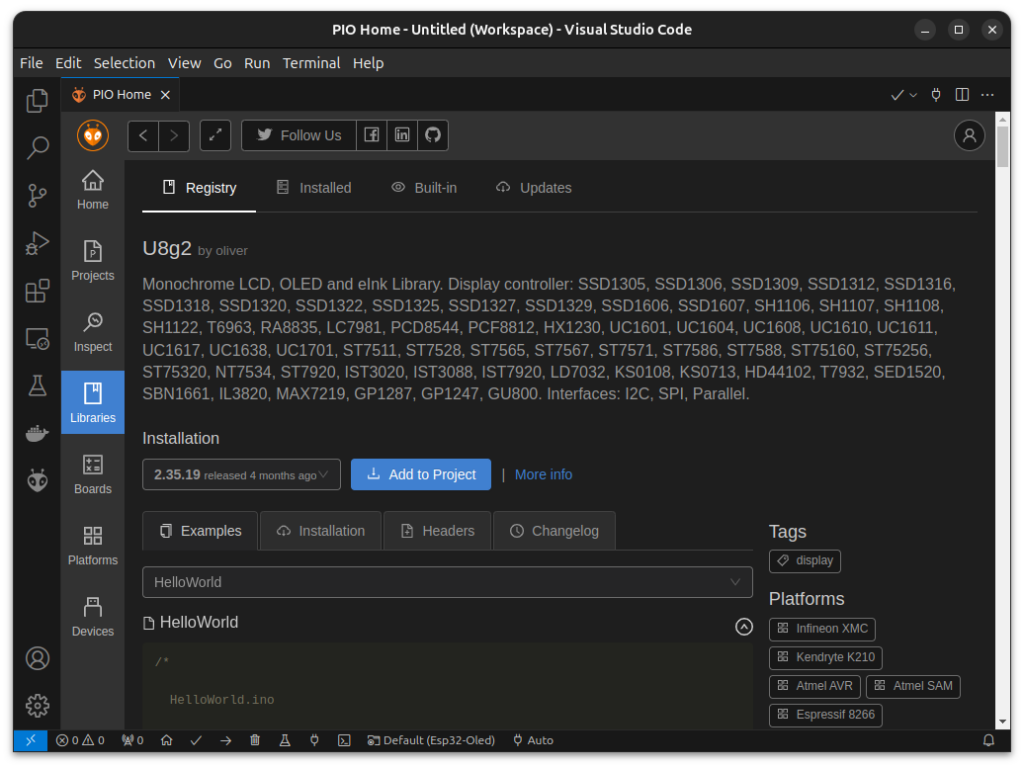
To install the Library we will be using, start by opening the ‘PIO Home’, then click on ‘Libraries’ and search for ‘U8g2’ in the ‘Registry’.
After finding the correct library, click ‘Add to Project’ and choose the one you want to install the library to.
After the library finishes downloading, we can start coding.
2 - Code
For this small tutorial we will need, ‘Arduino.h’ and ‘U8g2lib.h’. As for the variables, we will have an int named ‘pos’ to keep track of the position of a square that will be displayed in the screen, and the oled screen itself. Choosing it can be a little overwhelming, but you can press ‘ctrl+space’ in VSCode and get auto completion, so, if you know it is a ‘SSD1306 128×32’ display that uses ‘I2C’ to connect, then you only have some options to choose from.
You should also choose the ‘HW’ (hardware) version, if possible, as it is faster (higher refresh rate). The ‘F’ also tells you that the display will only render when you call ‘oled.sendBuffer’.
#include <Arduino.h>
#include <U8g2lib.h>

U8G2_SSD1306_128X32_UNIVISION_F_HW_I2C oled(U8G2_R0);
// The x position of the square on screen
int pos = 0;
For the setup, we only need to call one function, it simply starts the display.
void setup()
{
    // Start the display
    oled.begin();
}
In the main loop is where stuff really happens. We start by calculating the position where we want to draw the square at, then, clear the current buffer, so that the stuff that was drawn before does not get drawn again, then we draw the stuff we want to see in the display, in this case, a square 20px wide and, finally, we send the buffer to the display.
I also added a little delay but that is completely optional.
void loop()
{
    // calculate next position (between 0 and 108)
    pos = (pos + 1) % (128 - 20);

    // Clear buffer (NOT THE DISPLAY)
    oled.clearBuffer();
    // Draw 20 wide square
    oled.drawBox(pos, 6, 20, 20);
    // Send buffer to display
    oled.sendBuffer();

    // Optional delay (1ms)
    vTaskDelay(1 / portTICK_PERIOD_MS);
}
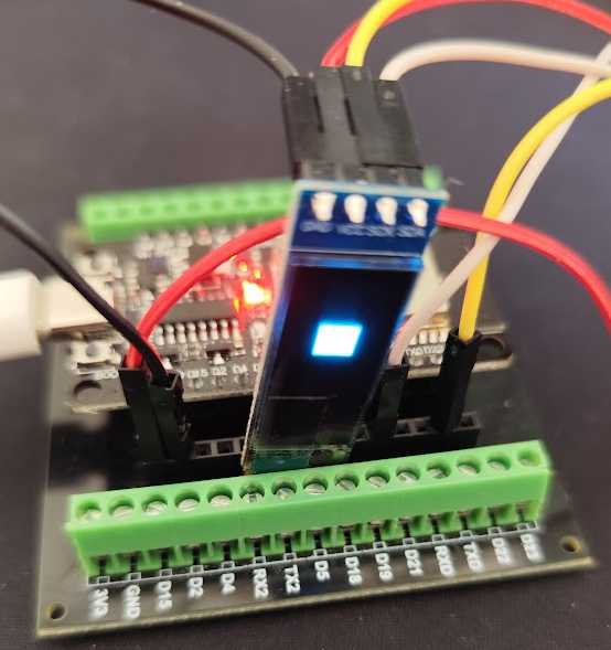
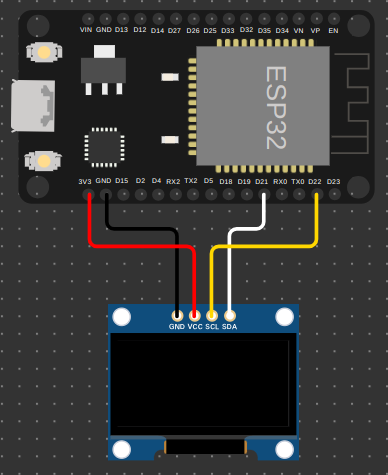
Now, with the code done, we can move on to assembling the circuit.
I made a Wokwi diagram for those of you that want to test the circuit without having to buy and assemble it.
Keep in mind that, if you use Wokwi, you also need to add the U8g2 library at the Library Manager.
Here is the diagram I used, just don’t forget to add the U8g2 library:
{
  "version": 1,
  "author": "Anonymous maker",
  "editor": "wokwi",
  "parts": [
    { "type": "wokwi-esp32-devkit-v1", "id": "esp", "top": -43.9, "left": 99, "rotate": 90, "attrs": {} },
    { "type": "board-ssd1306", "id": "oled1", "top": 166.34, "left": 105.83, "attrs": { "i2cAddress": "0x3c" }
    }
  ],
  "connections": [
    [ "esp:TX", "$serialMonitor:RX", "", [] ],
    [ "esp:RX", "$serialMonitor:TX", "", [] ],
    [ "esp:21", "oled1:SDA", "white", [ "h24.04", "v-76.8", "h9.6" ] ],
    [ "esp:GND.1", "oled1:GND", "black", [ "v18.9", "h38.5" ] ],
    [ "esp:D21", "oled1:SDA", "white", [ "v18.9", "h-18.87" ] ],
    [ "esp:D22", "oled1:SCL", "gold", [ "v28.5", "h-57.6" ] ],
    [ "esp:3V3", "oled1:VCC", "red", [ "v28.5", "h57.6" ] ]
  ],
  "dependencies": {}
}
And that’s it, thanks for reading, and stay tuned for more tech insights and tutorials. Until next time, and keep exploring the world of tech!