0 - Introduction
If you are thinking of your next project you might be wondering which input method would be the best choice. The Rotary Encoder is, in use, similar to the Potentiometer, but in code, very different. It is actually a little complex to set it up in a good way to work with and, because of that, we will be using a library named ‘Ai Esp32 Rotary Encoder’.
Requirements:
- Esp32 (like this one)
- Rotary Encoder (like this one)
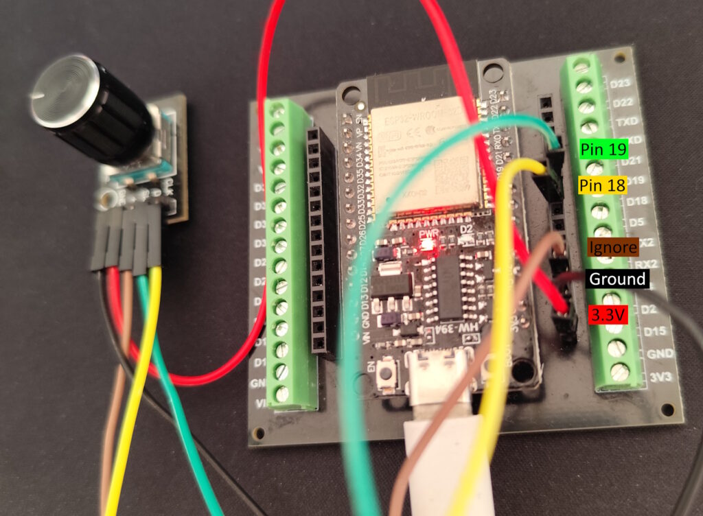
- At least 4 wires (like these ones)

1 - Install Library
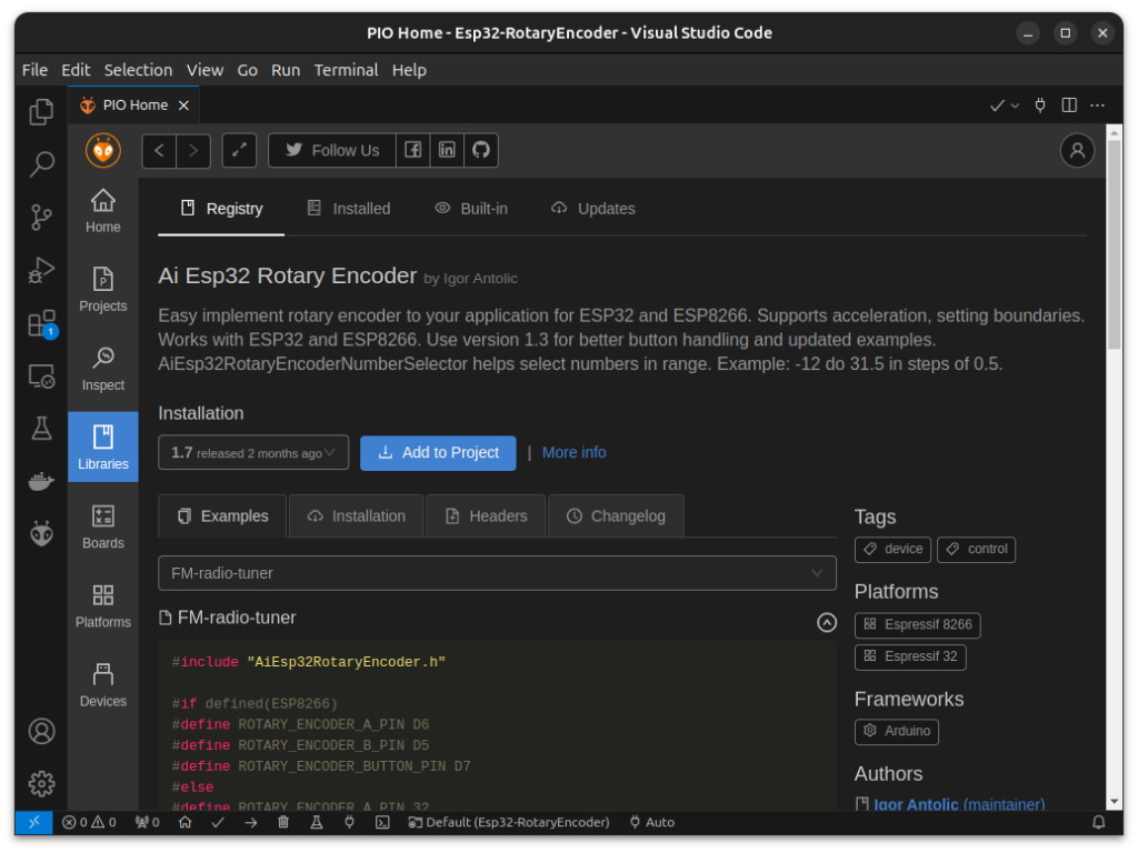
To install the Library we will be using, start by opening the ‘PIO Home’, then click on ‘Libraries’ and search for ‘AI Esp32 Rotary Encoder’ in the ‘Registry’.
After finding the correct library, click ‘Add to Project’ and choose the one you want to install the library to.
After the library finishes downloading, we can start coding.

2 - Code
Let’s start by including the necessary headers and defining the pins we will be using:
#include <Arduino.h>
// The encoder itself
#include <AiEsp32RotaryEncoder.h>
// Helper, great for making menus and sliders
#include <AiEsp32RotaryEncoderNumberSelector.h>

// If you want the encoder to increase in the
// oposite direction, switch pin A with pin B
// Clock or Data pin
#define ROTARY_ENCODER_A_PIN 19
// Clock or Data pin
#define ROTARY_ENCODER_B_PIN 18
// Change to the one that fits your encoder the
// best, recommended values are 1, 2 and 4
#define ROTARY_ENCODER_STEPS 2
Now, we create the variables we will be using:
AiEsp32RotaryEncoder* enc = new AiEsp32RotaryEncoder(ROTARY_ENCODER_A_PIN,
                     ROTARY_ENCODER_B_PIN, -1, -1, ROTARY_ENCODER_STEPS);
AiEsp32RotaryEncoderNumberSelector nenc = AiEsp32RotaryEncoderNumberSelector();
We will need a function that might seam a little strange, but it’s use is to be called by the interrupts and update the values of our encoder:
void IRAM_ATTR readEncoderISR() { enc->readEncoder_ISR(); }
Then, we need to create the setup function:
void setup()
{
    // Open serial and wait 2.5 seconds
    Serial.begin(115200);
    vTaskDelay(2500 / portTICK_PERIOD_MS);

    // Start encoder and set interrupt callback
    enc->begin();
    enc->setup(readEncoderISR);
    // Setup Number Selector
    nenc.attachEncoder(enc);
    // Set min, max, increment and whether it should loop
    nenc.setRange(0, 1, 0.01, true);
    // Set initial value to 0
    nenc.setValue(0);
}
And finally, on loop, we send a message, via Serial, if the encoder value changed:
void loop()
{
    if (enc->encoderChanged())
        Serial.printf("%.2f\n", nenc.getValue());
}
Now, with the code done, we can move on to assembling the circuit.
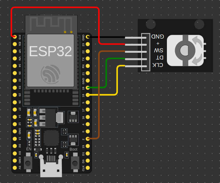
I made a Wokwi diagram for those of you that want to test the circuit without having to buy and assemble it.
Keep in mind though, that the Wokwi Rotary Encoder is a little weird to mess with, setting ‘ROTARY_ENCODER_STEPS’ to 4 seams to give better results, even though my IRL Rotary Encoder works fine with 2, and even 1 works, if you can tolerate some inaccuracies.

Just paste the json below in ‘diagram.json’.
{
  "version": 1,
  "author": "Anonymous maker",
  "editor": "wokwi",
  "parts": [
    { "type": "board-esp32-devkit-c-v4", "id": "esp", "top": 0, "left": -4.76, "attrs": {} },
    {
      "type": "wokwi-ky-040",
      "id": "encoder1",
      "top": 5.1,
      "left": 144,
      "rotate": 180,
      "attrs": {}
    }
  ],
  "connections": [
    [ "esp:TX", "$serialMonitor:RX", "", [] ],
    [ "esp:RX", "$serialMonitor:TX", "", [] ],
    [ "esp:GND.2", "encoder1:GND", "black", [ "v0" ] ],
    [ "esp:3V3", "encoder1:VCC", "red", [ "h-4.61", "v-38.4", "h115.2", "v48" ] ],
    [ "esp:18", "encoder1:CLK", "gold", [ "h38.4", "v-38.4" ] ],
    [ "esp:19", "encoder1:DT", "green", [ "h24.04", "v-38.4" ] ],
    [ "esp:2", "encoder1:SW", "#8f4814", [ "h14.44", "v-115.2" ] ]
  ],
  "dependencies": {}
}
And that’s it! The Rotary Encoder I suggested also has a button, which can be either, used like any other button, or used with the library.
Thanks for reading and stay tuned for more tech insights and tutorials. Until next time, and keep exploring the world of tech!
