
Keeping track of your home lab’s server status doesn’t have to mean logging into a dashboard or constantly checking your phone. With an ESP32 and an e-paper display, you can create a low-power, always-on status panel that provides real-time updates on your servers’ availability at a glance.
In this guide, we’ll walk through building a compact, efficient monitoring system using a CrowPanel e-paper display. We’ll cover everything from setting up the hardware and writing the software to displaying ‘real-time pings’ (once every two minutes) with custom icons. Whether you’re a home lab enthusiast or just looking for a fun ESP32 project, this tutorial will help you build a practical and cool server monitor.
For this project, we will need a CrowPanel 5.79”, any SD Card and a USB-C cable. On the software side we will need VS Code, Python3 with Pillow and PlatformIO.
You can get VS Code here and PlatformIO is installed on VS Code’s extensions tab. You can download Python3 here or you can also install it by running:
sudo apt install python3Finally, you can install Pillow by running one of the following commands:
python3 -m pip install pillow
# or
pip install pillow
Let’s now create our project folder and, in it, a file named ‘platformio.ini’ with the contents below inside it:
mkdir CrowPanel-Ping
cd CrowPanel-Ping
nano platformio.ini
[env:esp32-s3-devkitc-1]
platform = espressif32
board = esp32-s3-devkitc-1
framework = arduino
board_build.arduino.memory_type = qio_opi
board_build.flash_mode = qio
board_build.psram_type = opi
board_upload.flash_size = 8MB
board_upload.maximum_size = 8388608
board_build.extra_flags =
-DBOARD_HAS_PSRAM
lib_deps =
bblanchon/ArduinoJson@^7.2.0
marian-craciunescu/ESP32Ping@^1.7
After creating the ini file, open VSCode inside the project folder:
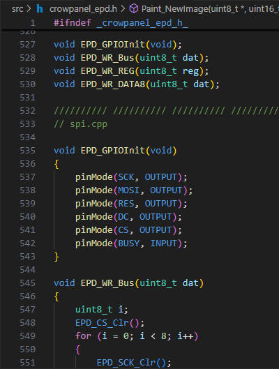
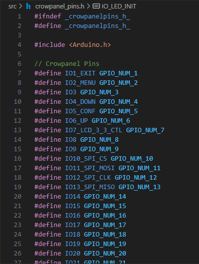
code .Once inside VS Code, you will also need Elecrow’s EPD library for this display, you can either get it on their GitHub or the single file solution we made. Besides the display’s library, we also made a file with defines for all the CrowPanel’s pins, so that you won’t need to be always looking at the datasheet or photos in the store page.
Download both header files by clicking the images below and paste them inside the ‘src’ directory:
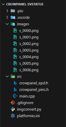
Your project folder should look like this after ‘platformio.ini’, adding the CrowPanel headers, and creating the main file:
CrowPanel-Ping
├── platformio.ini
└── src
    ├── crowpanel_epd.h
    ├── crowpanel_pins.h
└── main.cppTo be able to display pictures on your CrowPanel, you can’t just send it a PNG file. First, we need to convert it into binary and then, either load them from the SD Card (medium difficulty) or load them from a header file (easy), which is what we are going to do.
Start by downloading the images below and place them inside a folder named ‘images’ on your project’s folder:
After getting the images, let’s set up the script to convert them. Create a python script named ‘imgconvert.py’ at the root of your project. In that file, paste the code below:
🐍 Python Script
import os # used for file access
import re # used for string formatting
from PIL import Image # used for image convertion
# to install pillow run
# 'pip install pillow' or 'python3 -m pip install pillow'
# Input directory
path = "images"
# Start Header file
output = "#ifndef IMAGES_H_\n#define IMAGES_H_\n\n#include <Arduino.h>\n\n"
# Convert bytes to C array
def bytesToCArr(filename: str, data: bytearray) :
global output # Get output variable
fname = filename.replace('.', '_') # change dots in file name to underlines
fsize = str(len(data)) # calculate file size (not the PNG file, the binary conversion)
beginstr = "static const uint8_t img_" + fname + "[" + fsize + "] = {\n\t" # declare array
contentstr = "{}".format(", ".join([format(b, '#04x') for b in data])) # add data as hex uint8
splitstr = beginstr + re.sub("(.{72})", "\\1\n\t", contentstr, count=0, flags=re.DOTALL) + "\n};\n" # separate lines
finalstr = splitstr + "static const uint32_t img_size_" + fname + " = " + fsize + ";\n\n" # add array size constant
output += finalstr # add c code to output string
# Convert Image to bytes
def imgToBin(filename: str, w: int, h: int) -> bytearray:
with Image.open(os.path.join(path, filename)) as img: # open image
if w == 0 or h == 0: # if no width and height given
w = img.width # use original size
h = img.height
# resize, to monochrome and to binary
return bytearray(img.resize((w, h)).convert("1").tobytes())
# Foreach file in input directory
for filename in os.listdir(path):
if filename.endswith(".png") or filename.endswith(".jpg"): # if png or jpg
bindata = imgToBin(filename, 0, 0) # convert to binary
bytesToCArr(filename, bindata) # convert to C Array and add to output
# Add end of file
output += "#endif\n"
# Write to file
outpath = os.path.join("src", "images.h")
with open(outpath, "w") as f:
f.write(output)
# Print output path
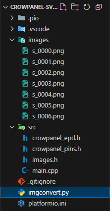
print(outpath)Now every time you execute the python script above, all your images are converted into C Arrays in a file named ‘images.h’ inside your source directory. By looking at the images below, you can get an idea of how it works:
You can run the script with the following command (should work both on Ubuntu and Windows):
python3 imgconvert.pyIf you then check your new file, you should see all PNG files inside your images folder converted into byte arrays:
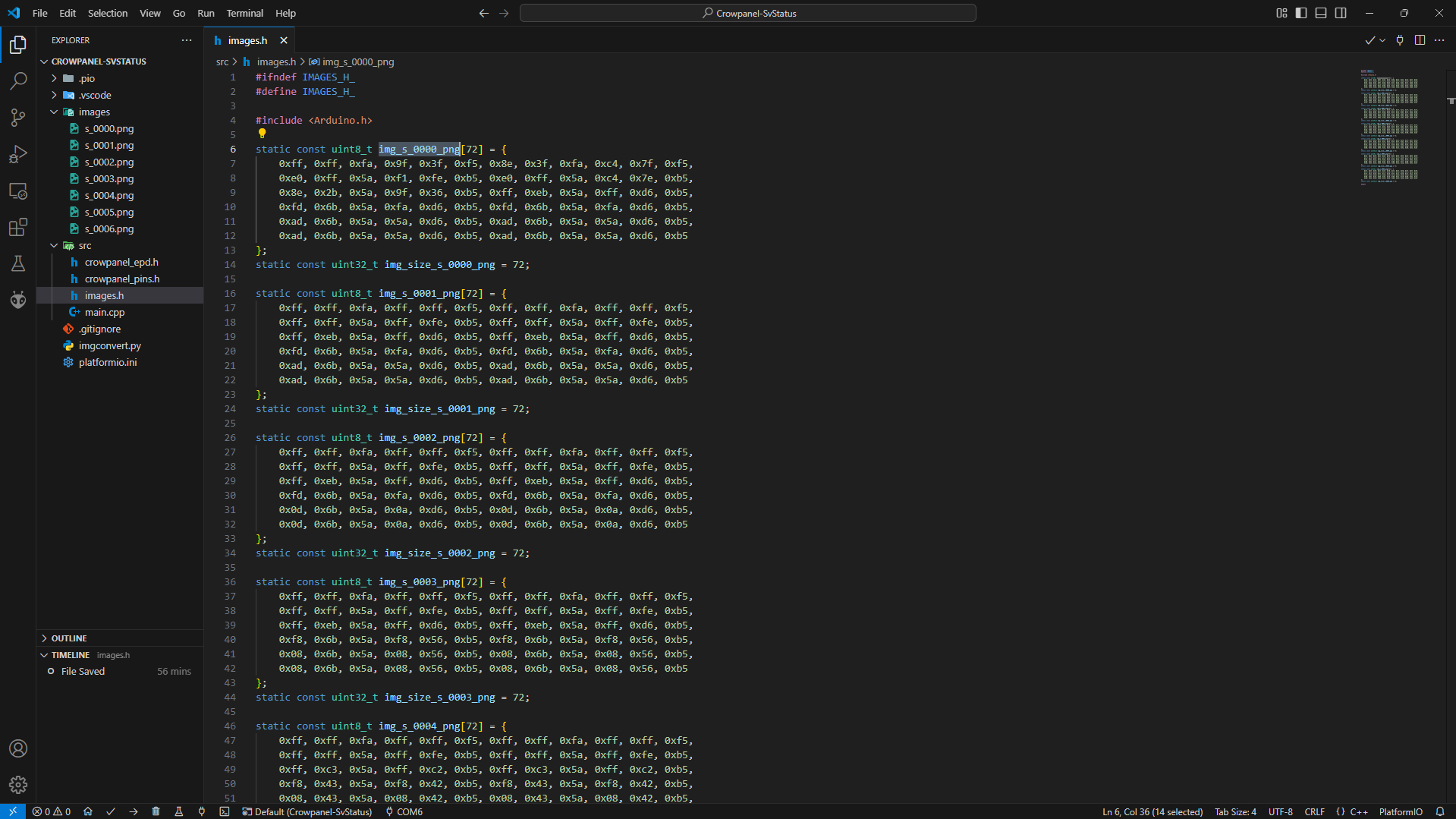
Every time you change the contents of the ‘images’ folder, you should also re-run the ‘imgconvert’ script.
Now that we have everything setup, let’s make our application. The first thing we need to do is to include some header files (main.cpp):
#include <Arduino.h>
#include <SPI.h> // Used to communicate with the SD card
#include <SD.h>  // Used to access the SD Card's files
#include <ArduinoJson.h> // Used to load the config
#include <ESP32Ping.h>   // Used to ping hosts
#include "crowpanel_pins.h" // CrowPanel's Pin definitions
#include "crowpanel_epd.h"  // CrowPanel's Display control
#include "images.h" // Images in C Array format
Then we need some constants. By default, the Esp sleeps for 2 minutes. The max host count and name sizes should remain unchanged, as they are dependent on the font size we will use later and the screen size. The config path is the path to the file where that config will be loaded from (should always start with the character ‘/’). Finally, the button wake-up mask tells the Esp32 which buttons should wake it up from sleep, in this case, only the menu and exit buttons and not the rocker switch:
// Default sleep time in seconds
const int DEFAULT_SLEEP_TIME = 120;
// Max ammount of hosts that can be displayed on the screen
const int MAX_HOST_COUNT = 25;
// Max ammount of characters that can be displayed on screen per line
const int MAX_HOST_NAME_SIZE_EPD = 16; // 15 chars + '\0'
// Config path
const char* configPath = "/config.json";
// Which buttons wake up the esp from sleep
const uint64_t button_wakeup_mask = (1ULL << IO2_MENU) | (1ULL << IO1_EXIT);
Next come the variables that will be loaded from the config file. Besides the config variables, we will also need a big ‘uint8’ array to be our draw buffer. We will draw our image to this buffer and then send it to the display to be displayed:
// Sleep time in seconds
uint64_t sleepWakeupTime = DEFAULT_SLEEP_TIME;
// WiFi creds
String wifi_ssid = "jpmv2020-Lptp";
String wifi_pass = "qwertyuiop";
// Hosts
String ping_ips[MAX_HOST_COUNT];
uint8_t ping_ipc = 0;
// Time
int time_gmtoffset = 0;
int time_dstoffset = 0;

// Draw buffer
uint8_t drawbuf[27200];
Now let’s start implementing our functions. The first one will be called ‘initSD’ and its job is going to be to initialize the SD Card and log its type to Serial:
// Initialize SD Card
bool initSD()
{
    // Turn SD card reader on
    pinMode(IO_SD_POWER, OUTPUT);
    digitalWrite(IO_SD_POWER, HIGH);
    // sleep 10ms to give time for the SD card reader to turn on
    vTaskDelay(10 /portTICK_PERIOD_MS);
    // setup spi
    SPI.begin(IO_SD_CLK, IO_SD_MISO, IO_SD_MOSI, IO_SD_CS);
    // Setup SD
    if (!SD.begin(IO_SD_CS))
    {
        Serial.println("SD: No card detected");
        return false;
    }
    switch (SD.cardType())
    {
        case CARD_NONE: Serial.println("SD: No card detected"); return false;
        case CARD_MMC: Serial.println("SD: Detected card of type MMC"); break;
        case CARD_SD: Serial.println("SD: Detected card of type SD"); break;
        case CARD_SDHC: Serial.println("SD: Detected card of type SDHC"); break;
        case CARD_UNKNOWN:
        default:
            Serial.println("SD: Unsupported SD card");
            return false;
    }
    return true;
}
The ‘loadConfig’ function’s job is to open the config file, check that every field is present and load it. If this process fails, the Esp will log to Serial and enter sleep. This repeats until this process passes.
// Loads config from SD card
bool loadConfig()
{
    // Open config fail
    fs::File f = SD.open(configPath);
    // Does not exist?
    if (!f)
    {
        Serial.printf("SD: Can't open %s\n", configPath);
        return false;
    }
    // Read file contents
    char readbuf[2048];
    size_t readBytes = f.readBytes(readbuf, 2048);
    if (!readBytes)
    {
        Serial.println("SD: Empty config file");
        return false;
    }

    // Json text to document
    JsonDocument doc;
    deserializeJson(doc, readbuf);

    // Get sleep time
    if (doc.isNull() || !doc["sleepTime"].is<uint64_t>())
    {
        Serial.println("SD: Invalid or null sleepTime");
        return false;
    }
    sleepWakeupTime = doc["sleepTime"].as<uint64_t>();

    // Get Time offsets
    JsonObject time = doc["time"];
    if (time.isNull() || !time["gmt"].is<int>() || !time["dst"].is<int>())
    {
        Serial.println("SD: Invalid or null time.gmt and time.dst");
        return false;
    }
    time_gmtoffset = time["gmt"].as<int>();
    time_dstoffset = time["dst"].as<int>();

    // Get WiFi creds
    JsonObject wifi = doc["wifi"];
    if (wifi.isNull() || !wifi["ssid"].is<String>() || !wifi["pass"].is<String>())
    {
        Serial.println("SD: Invalid or null wifi.ssid and wifi.pass");
        return false;
    }
    wifi_ssid = wifi["ssid"].as<String>();
    wifi_pass = wifi["pass"].as<String>();

    // Get hosts
    JsonArray hosts = doc["hosts"];
    if (hosts.isNull() || hosts.size() <= 0)
    {
        Serial.println("SD: Invalid or null hosts array");
        return false;
    }

    // Clamp hosts array
    size_t hostc = hosts.size();
    ping_ipc = hostc > MAX_HOST_COUNT ? MAX_HOST_COUNT : hostc;
    // Iterate over each host
    uint8_t i = 0;
    for (JsonVariant v: hosts)
    {
        // Check if it is a string
        if (!v.is<String>())
            continue;
        // Save to hosts array
        ping_ips[i] = v.as<String>();
        // Check if array is full
        if (++i >= ping_ipc)
            break;
    }
    // No valid hosts? fail
    if (!i)
    {
        Serial.println("SD: No valid host in hosts array");
        return false;
    }

    return true;
}
‘wifi_connect’ job is to not only connect to Wi-Fi, but also to set up time. This function will begin connecting, if it can’t in 15 secs, the Esp will enter sleep, if it connected successfully, it will configure the time and log the offsets set in the configuration file:
// Connects to WiFi and gets time data
void wifi_connect()
{
    // Connect
    WiFi.begin(wifi_ssid, wifi_pass);
    Serial.printf("Connecting to %s", wifi_ssid);
    while (WiFi.status() != WL_CONNECTED) // Wait until connected
    {
        Serial.print('.');
        vTaskDelay(100 / portTICK_PERIOD_MS);
        // Waited for 15 secs and no connection? sleep
        if (millis() > 15000)
        {
            Serial.println("\nCan't connect to WiFi, going to sleep...");
            vTaskDelay(100 / portTICK_PERIOD_MS);
            esp_deep_sleep_start();
        }
    }
    Serial.printf("\nConnected to %s (%s)\n", wifi_ssid, WiFi.localIP().toString().c_str());

    // Setup NTP to get time
    configTime(time_gmtoffset * 3600, time_dstoffset * 3600, "pool.ntp.org");
    Serial.printf("Time Settings: GMT %s%02d:00, DST %s%02d:00\n",
        time_gmtoffset < 0 ? "-":"+", time_gmtoffset < 0 ? time_gmtoffset * -1:time_gmtoffset,
        time_dstoffset < 0 ? "-":"+", time_dstoffset < 0 ? time_dstoffset * -1:time_dstoffset);
}
The ‘getPing’ function receives a host address, then pings it and returns the pointer to the correct icon to display:
// Pings a host and returns the correct icon
const uint8_t* getPing(String& adr)
{
    // Ping address 2 times
    if (!Ping.ping(adr.c_str(), 2))
    {
        Serial.printf("[%s] Could not ping\n", adr.c_str());
        return img_s_0000_png;
    }
    // Get latency
    float ms = Ping.averageTime();
    Serial.printf("[%s] Pinged: %.2fms\n", adr.c_str(), ms);
    if (ms < 20)
        return img_s_0006_png;
    if (ms < 60)
        return img_s_0005_png;
    if (ms < 100)
        return img_s_0004_png;
    if (ms < 150)
        return img_s_0003_png;
    if (ms < 200)
        return img_s_0002_png;
    return img_s_0001_png;
}
The ‘initDisplay’ function sets up the pins to use the display, hardware resets it to avoid unexpected errors and then initializes our draw buffer:
// Initializes the display
void initDisplay()
{
    // Enable power to the display
    pinMode(IO_EPD_POWER, OUTPUT);
    digitalWrite(IO_EPD_POWER, HIGH);
    // Init display's pins
    EPD_GPIOInit();
    // Hardware reset display
    EPD_HW_RESET();
    // Initialize draw buffer
    Paint_NewImage(drawbuf, EPD_W, EPD_H, 270, WHITE);
}
The ‘draw’ function’s job is to draw the image to the buffer and sending it to the display. We start by clearing the buffer, then we draw a black border, for each host address (up to 25), trim the hostname to 16 characters (15 chars + ‘\0’), draw it, get the Ping, draw its icon and finally, we draw a line to act as a separator:
// Draw to display
void draw()
{
    // Clear buffer
    Paint_Clear(WHITE);

    // Black border
    EPD_DrawRectangle(0, 0, 19, 791, BLACK, 1);
    EPD_DrawRectangle(251, 0, 271, 791, BLACK, 1);
    EPD_DrawRectangle(0, 0, 271, 19, BLACK, 1);
    EPD_DrawRectangle(0, 771, 271, 791, BLACK, 1);

    // List start y
    uint16_t y = 25;
    char domainbuf[MAX_HOST_NAME_SIZE_EPD]; // Helper buf
    // For each address
    for (uint8_t i = 0; i < ping_ipc; i++)
    {
        strncpy(domainbuf, ping_ips[i].c_str(), MAX_HOST_NAME_SIZE_EPD); // Copy string to make sure it fits the screen
        domainbuf[15] = '\0'; // Make sure string is null terminated
        EPD_ShowString(25, y, domainbuf, 24, BLACK); // Display domain
        EPD_ShowPicture(222, y, 24, 24, getPing(ping_ips[i]), BLACK); // Get ping and display icon
        y += 26; // 24 + 2
        EPD_DrawLine(0, y, 271, y, BLACK); // Draw separator
        y += 3; // 1 + 2
    }
    // Get time
    struct tm timeinfo;
    char timestr[32];
    if (getLocalTime(&timeinfo))
        strftime(timestr, 63, "Last update %H:%M:%S", &timeinfo);
    else
        snprintf(timestr, 63, "Last update ??:??:??");
    // Show 'last update'
    EPD_ShowString(25, 754, timestr, 16, BLACK);

    // Draw
    EPD_FastMode1Init(); // init display
    EPD_Display_Clear(); // clear display
    EPD_Display(drawbuf); // draw buffer
    EPD_FastUpdate(); // update display
    EPD_DeepSleep(); // display goes to sleep
}
Even though we will set up our ‘setup’ function to never reach its end (the last thing in it is entering deep sleep), we still need to declare our ‘loop’ function. In this one, I log to serial and add a small delay. If we see this message in the Serial monitor, we know that something went wrong in the ‘setup’ function:
// Execution should never reach loop
// because the esp goes to sleep at
// the end of the setup function
void loop()
{
    Serial.println("Reached Loop?");
    delay(1000);
}
And finally, we reach our ‘setup’ function. We start by turning the power LED on, to know that it is working, then we set both the Menu and Exit buttons as input and also begin Serial communication:
void setup()
{
    // Turn on power LED
    IO_LED_INIT; IO_LED_ON;

    // Set buttons as input
    pinMode(IO_SW_MENU, INPUT);
    pinMode(IO_SW_EXIT, INPUT);

    // Setup Serial
    Serial.begin(115200);

    // ...
}
After initializing Serial, we need to handle how the Esp behaves if it is waking up and how it wakes up. In this case, when it wakes up, we will simply log what woke it up. As to how it wakes up, we will have two methods, the first one is by pressing one of the top buttons and the other is after, by default, 2 minutes:
void setup()
{
    // ...

    // Handle wakeup
    uint64_t wakeup_gpio;
    esp_sleep_wakeup_cause_t wakeup_cause = esp_sleep_get_wakeup_cause();
    switch (wakeup_cause)
    {
        case ESP_SLEEP_WAKEUP_EXT1:
            wakeup_gpio = esp_sleep_get_ext1_wakeup_status();
            if (wakeup_gpio & (1ULL << IO2_MENU))
                Serial.println("Wakeup: Btn Menu");
            else if (wakeup_gpio & (1ULL << IO1_EXIT))
                Serial.println("Wakeup: Btn Exit");
            else
                Serial.println("Wakeup: Btn Unknown");
            break;
        case ESP_SLEEP_WAKEUP_TIMER: Serial.println("Wakeup: Clock"); break;
        default: Serial.println("Wakeup: first boot"); break;
    }
    esp_sleep_enable_ext1_wakeup(button_wakeup_mask, ESP_EXT1_WAKEUP_ANY_LOW); // Wakeup from button
    esp_sleep_enable_timer_wakeup(1000000 * sleepWakeupTime); // Wakeup from clock

    // ...
}
The next step is to load the config. We start by initializing the SD card and then loading it. If one of those steps fail, the Esp will go to sleep:
void setup()
{
    // ...

    // Load config from SD
    if (!initSD() || !loadConfig())
    {
        sleepWakeupTime = DEFAULT_SLEEP_TIME;
        Serial.printf("SD: Can't load config from SD, going to sleep for %u seconds...\n", (uint32_t)sleepWakeupTime);
        esp_deep_sleep_start();
    }
    Serial.printf("SD: Loaded config (st: %u, hc: %u)\n", (uint32_t)sleepWakeupTime, (uint32_t)ping_ipc);

    // ...
}
To finish our ‘setup’ function, we connect to Wi-Fi, initialize and draw to the display and finally, log that we are done, turn the power LED off and put the Esp to sleep:
void setup()
{
    // ...

    // Connect to WiFi
    wifi_connect();

    // Init display and draw
    initDisplay();
    draw();

    // Turn off LED and sleep
    Serial.println("Screen update complete. Going to sleep...");
    IO_LED_OFF;
    esp_deep_sleep_start();
}
And that’s it for the code. You can now upload it to your CrowPanel.
At the root of your SD card, create a file named ‘config.json’ and, in it, place the configuration below. Make sure to change the Wi-Fi credentials and the hosts you want to ping:
{
    "time":
    {
        "gmt": 0,
        "dst": 0
    },
    "wifi":
    {
        "ssid": "WIFI_SSID_HERE",
        "pass": "************"
    },
    "sleepTime": 120,
    "hosts":
    [
        "localhost",
        "1.1.1.1",
        "8.8.8.8",
        "tmvtech.com",
        "l.tmvtech.com"
    ]
}
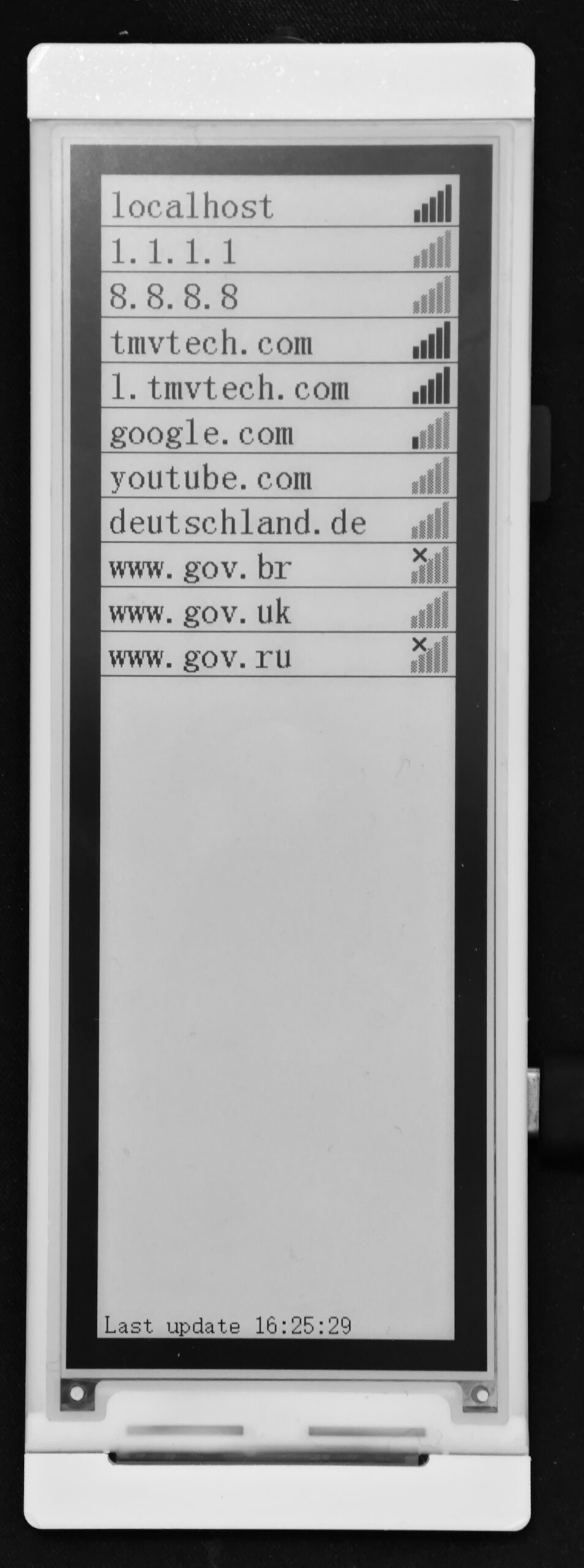
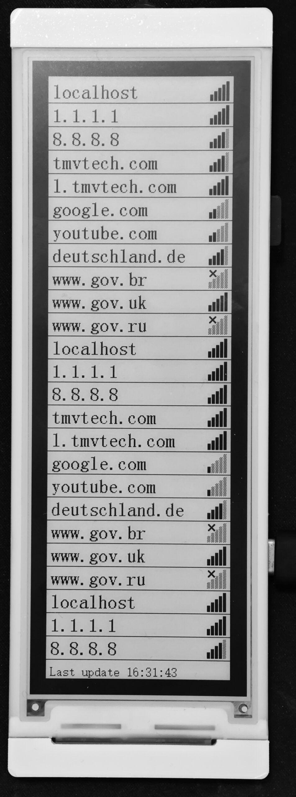
Below, you can then see how it all looks. On the first image, you can see how it looks with a couple of hosts, some from near me, other from far. For example, Russia’s and Brazil’s government websites are so far that the ping timed out. On the second image, you can see how it would look if you fill all the 25 host slots.
And that’s all. Thanks for reading and stay tuned for more tech insights and tutorials. Until next time, and keep exploring the world of tech!