
0 - Introduction
Just got your hands on the CrowPanel Advance 5.0? This guide will walk you through everything you need to set up your development environment on Windows. From installing the Arduino IDE to patching the ESP32-S3 core and uploading your first test code.
Whether you’re just starting out or already know your way around microcontrollers, this step-by-step setup will get you ready to build UIs and fully tap into what the CrowPanel has to offer.
1 - Install Arduino IDE
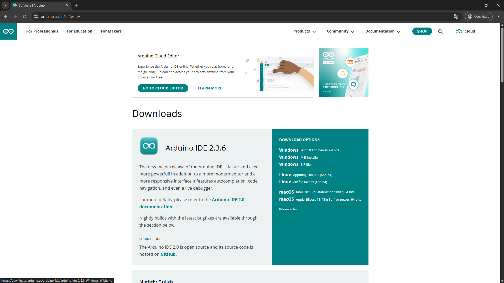
Let’s start by installing the Arduino IDE, go to Arduino’s website and download the Windows MSI Installer:
After downloading the MSI Installer, double click it to install the Arduino IDE. Once it is done, find the Arduino IDE in your start menu and open it.
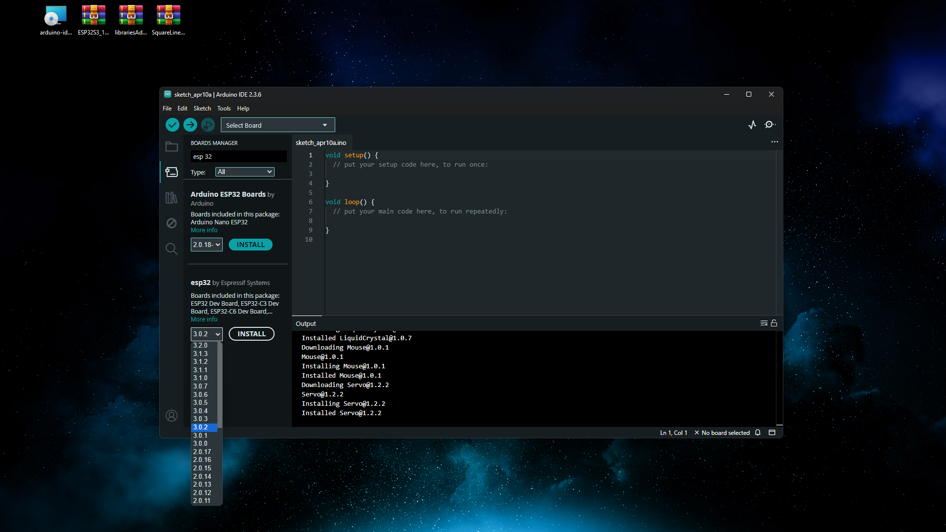
On the IDE, go to the Board Manager and download version 3.0.2 of the esp32 by Espressif:
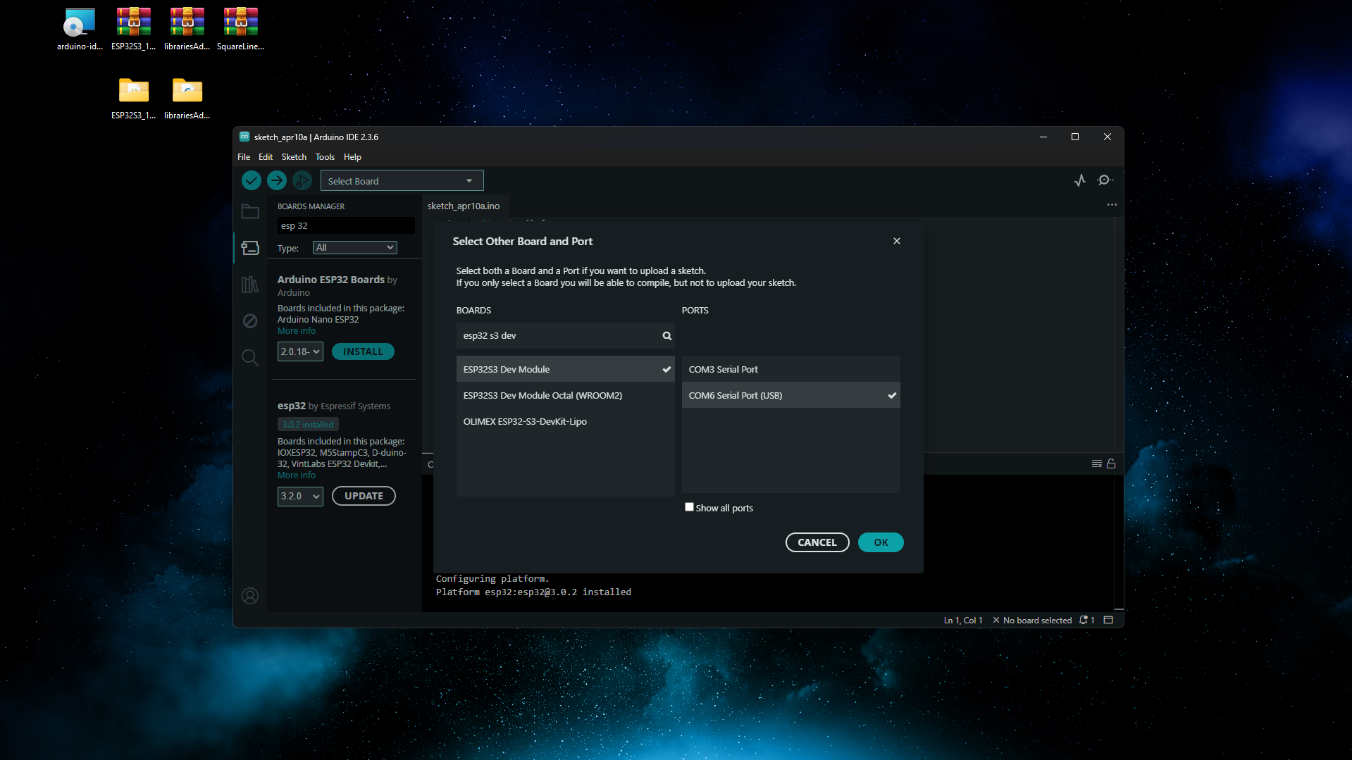
After it’s done installing, click on Select Board, select the ‘ESP32S3 Dev Module’ and the COM port. You can easily find your port by unplugging your CrowPanel and plugging it back in, seeing which port disappears and reappears.
2 - Patch Esp32 Package
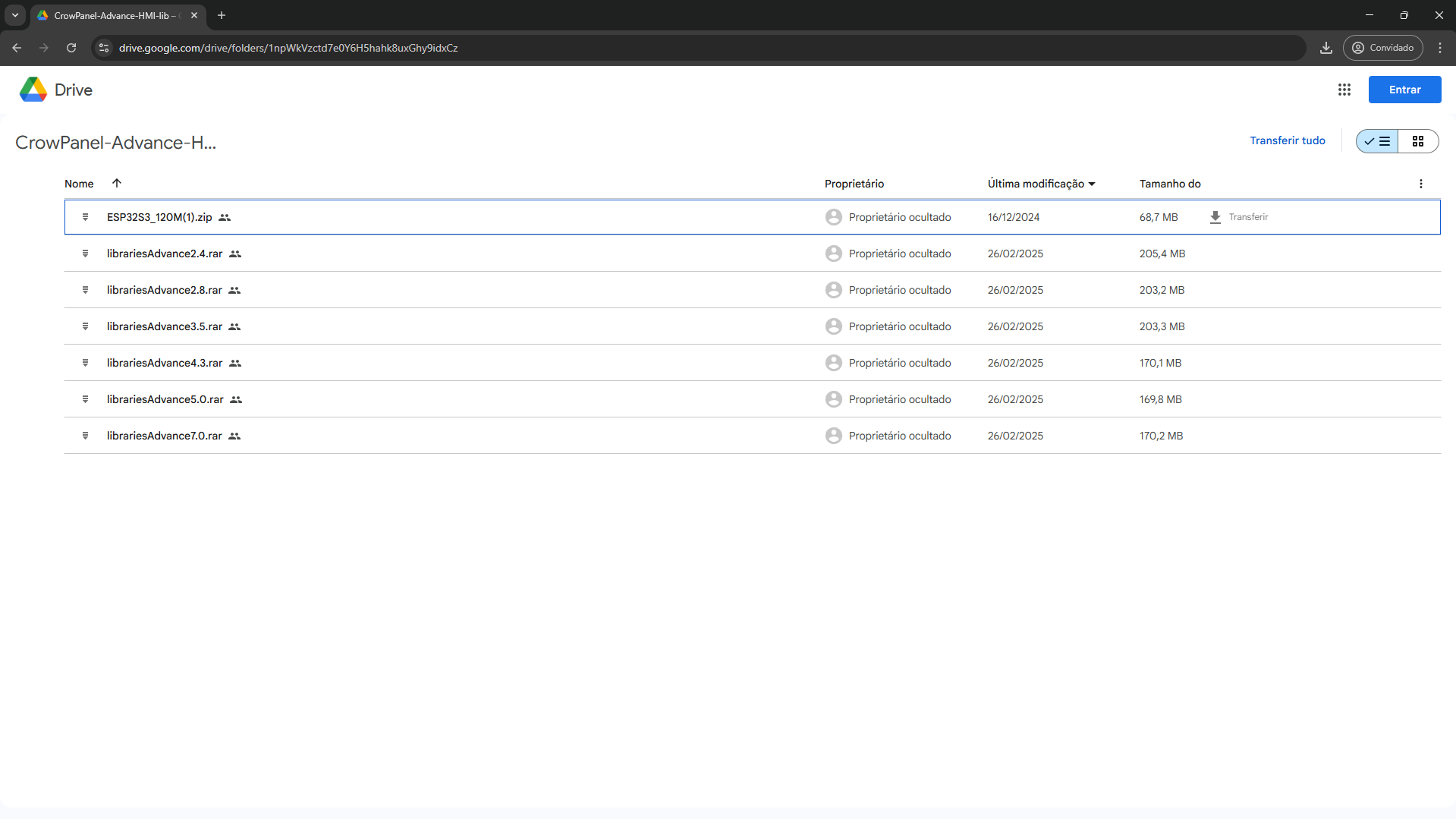
To be able to fully utilize your display, we will need to patch the Esp32’s firmware to be able to use the full speed of our PSRAM (120MHz instead of the usual 80MHz). For that, go to this Google Drive folder provided by Elecrow and download the ‘ESP32S3_120M.zip’ file:
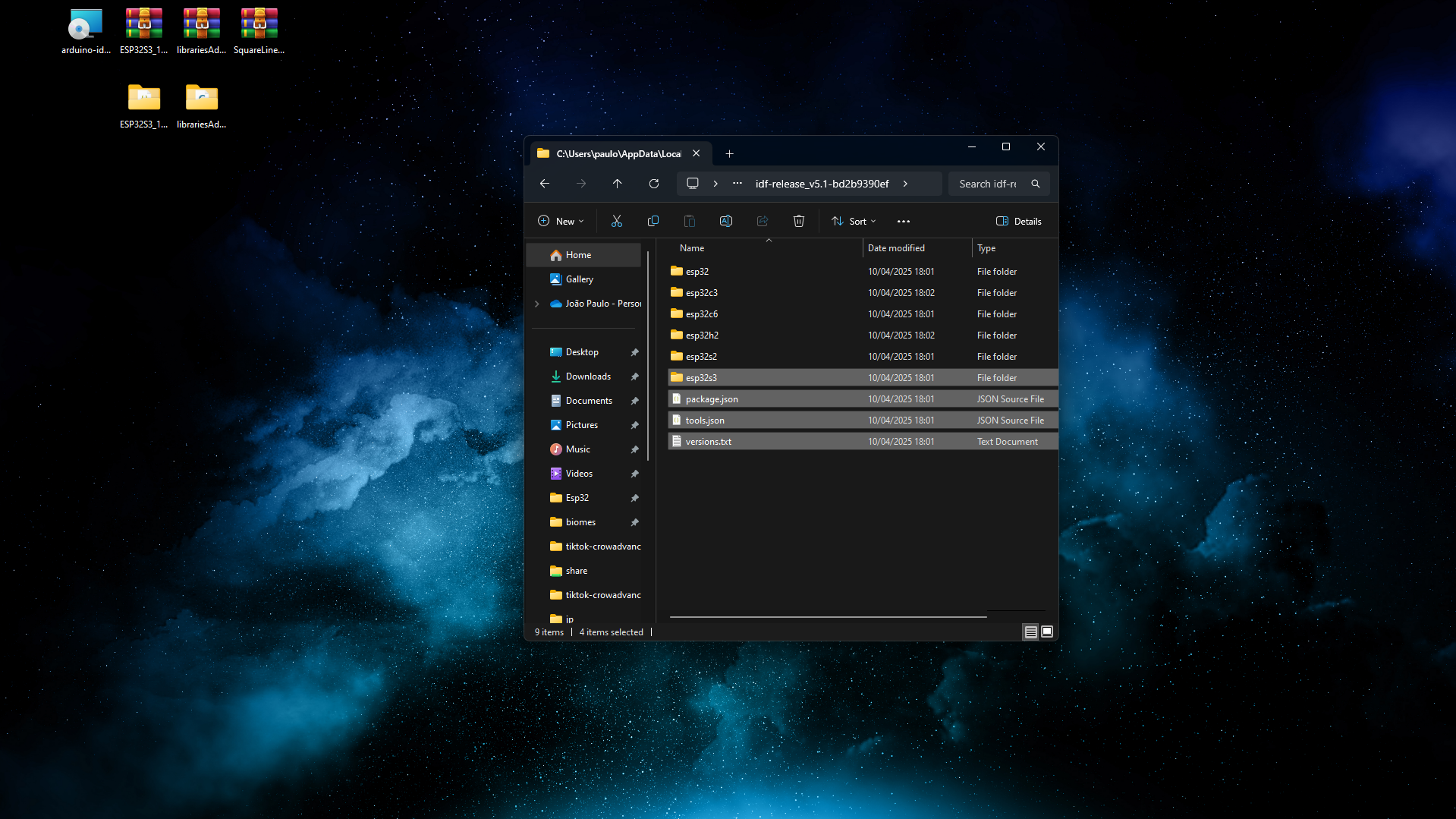
After downloading the archive, open a file explorer and go to the path below, replacing (username) with your username:
C:\Users\(username)\AppData\Local\Arduino15\packages\esp32\tools\esp32-arduino-libs\idf-release_v5.1-bd2b9390efOn that folder, delete the folder ‘esp32s3’ and the files ‘package.json’, ‘tools.json’ and ‘versions.txt’:
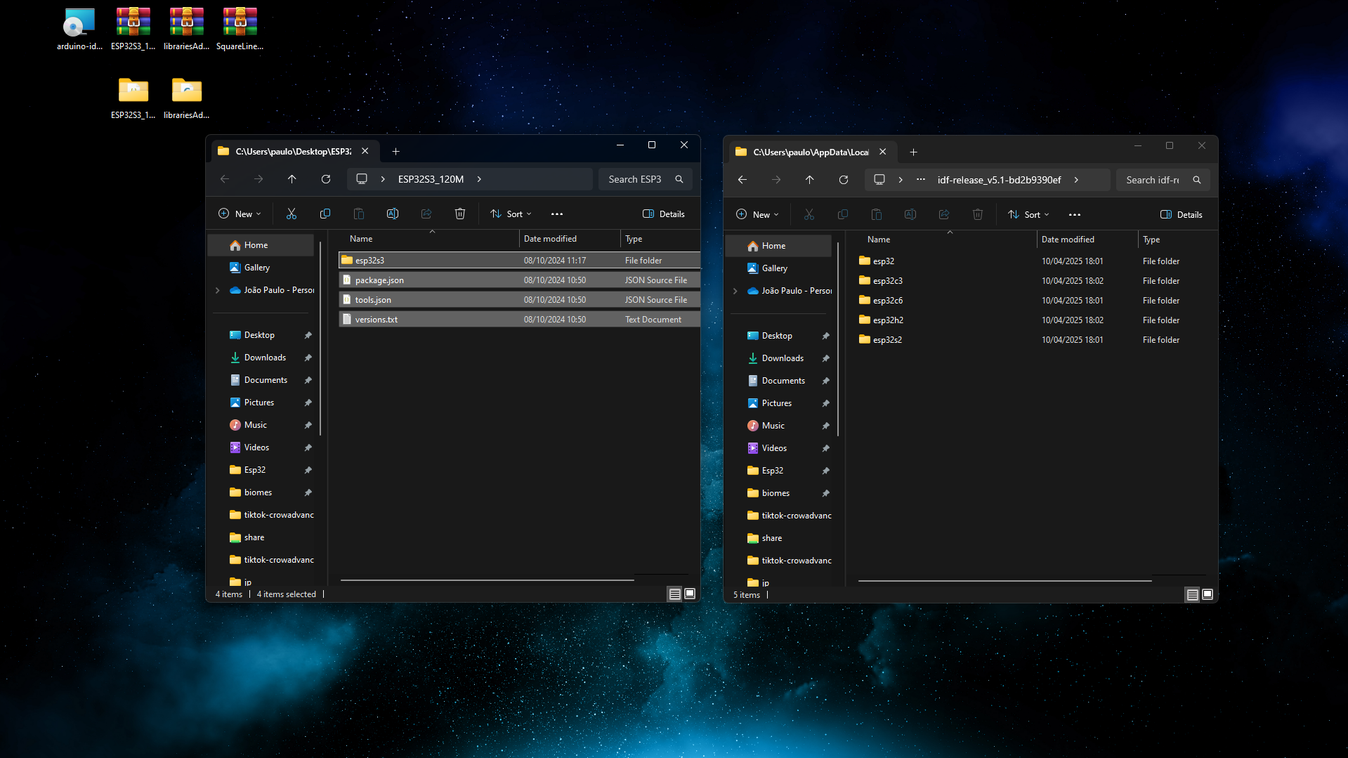
Extract the archive and move its contents to the folder:
3 - Install Libraries
On the Drive folder where we got the patched core from, download the libraries for your CrowPanel Advance, in my case, for the 5.0:
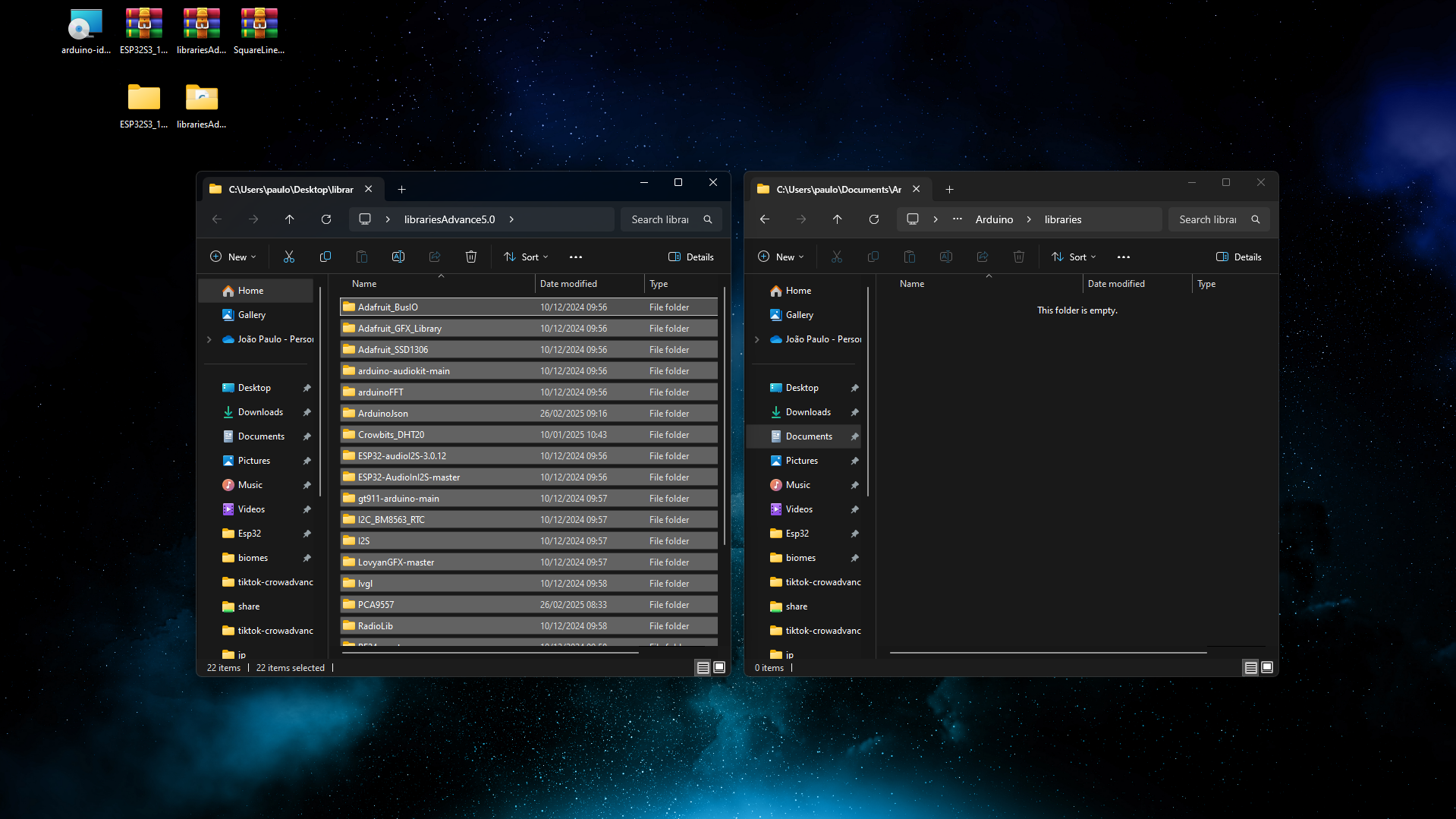
Go to the folder below, if it doesn’t exist, create it:
C:\Users\(username)\Documents\Arduino\librariesExtract your archive and move it’s contents into the Arduino Libraries folder:
4 - Upload your first code
Now we need to test if we can compile and send code to our CrowPanel. Copy the code below to your Arduino IDE:
#include <Arduino.h>

void setup()
{
    Serial.begin(115200);

    if (psramFound())
    {
        size_t psram_size = ESP.getPsramSize();
        Serial.println("PSRAM is available!");
        Serial.printf("PSRAM Size: %u bytes (%.2f MB)\n", psram_size, psram_size / (1024.0 * 1024.0));
    }
    else
    {
        Serial.println("PSRAM not available.");
    }
}

void loop()
{
    vTaskDelay(1000 / portTICK_PERIOD_MS);
}
On the top left of the Arduino IDE, click on ‘Tools’ and make sure the 3 settings highlighted on the picture below are the same ones you have selected:
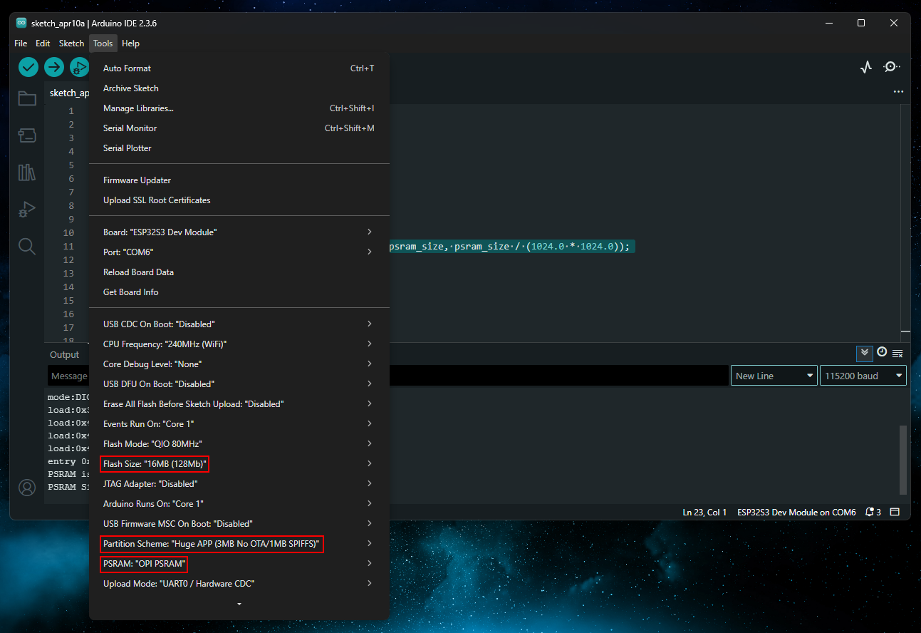
Then click on the Upload Arrow and wait until uploads. Then press CTRL+Shift+M to open the Serial Monitor, set its baud rate to 115200 and press the reset button on your CrowPanel. You should see an output similar to the one below:
PSRAM is available!
PSRAM Size: 8126464 bytes (7.75 MB)
5 - Install SquareLine Studio
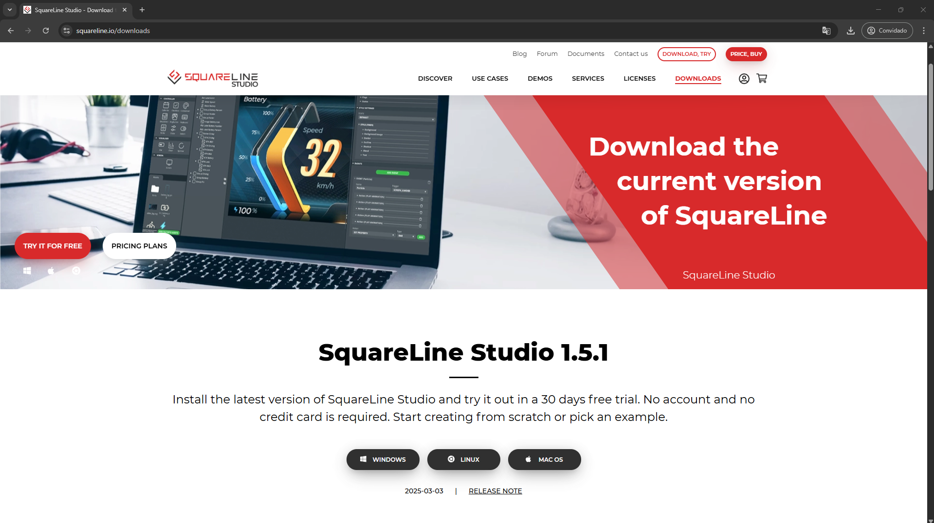
Go to SquareLine’s website and download SquareLine studio for Windows:
Open the installer and click ‘Install’:

Then click ‘Finish’ and open SquareLine Studio:
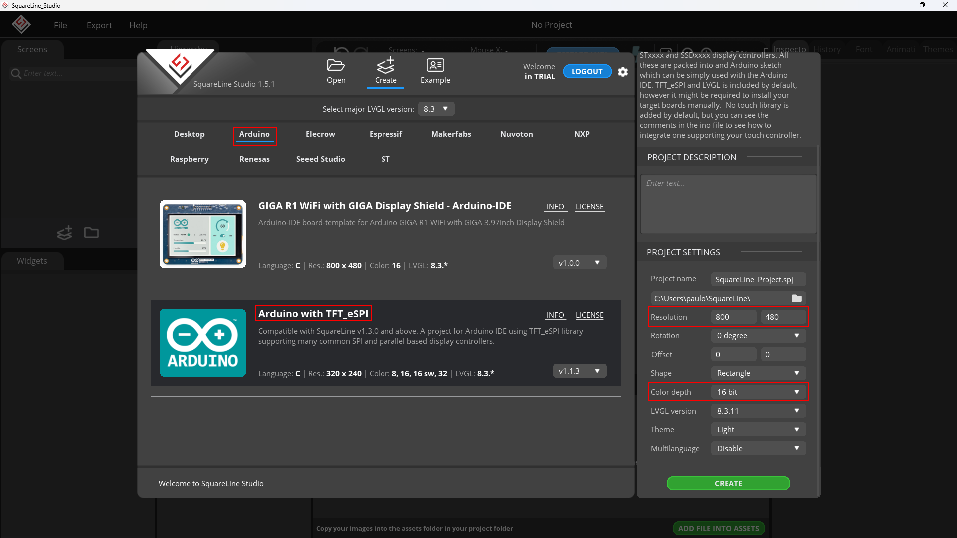
Create a new project and select ‘Arduino with TFT_eSPI’, on the right set the screen resolution to 800 by 480 and the color depth to 16 bits:
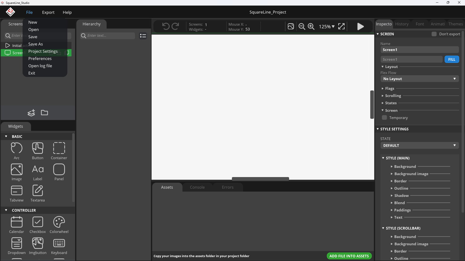
On the top left, click on ‘File’ and then ‘Project Settings’:
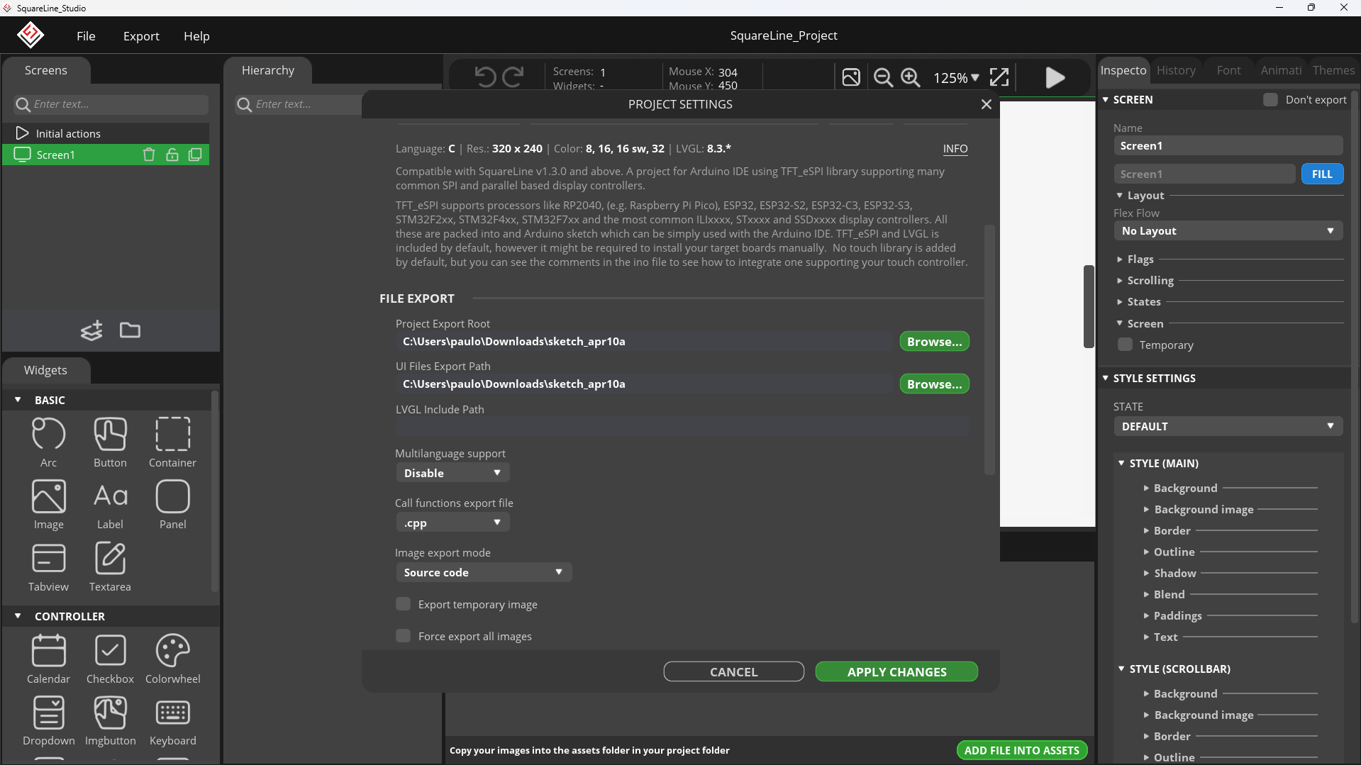
On ‘File Export’, set the ‘Project Export Root’ and ‘UI Files Export Path’ to your sketch’s folder and click ‘Apply’:
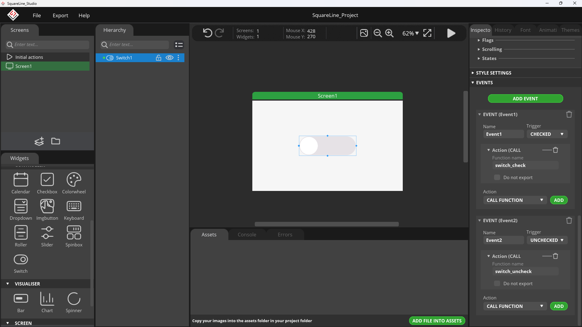
Add a switch to the center of your screen and then on the ‘Inspector’, look for events and add one for ‘CHECKED’ and one for ‘UNCHECKED’ with the actions being ‘Call a function’:
Then click on ‘Export’ on the top left and ‘Export UI Files’:

Back to the Arduino IDE, create a new file named ‘LovyanGFX_Driver.h’ and paste the code below. This code was taken from Elecrow’s Lesson 3.
#define LGFX_USE_V1
#include <LovyanGFX.hpp>
#include <lgfx/v1/platforms/esp32s3/Panel_RGB.hpp>
#include <lgfx/v1/platforms/esp32s3/Bus_RGB.hpp>
#include <driver/i2c.h>

class LGFX : public lgfx::LGFX_Device
{
public:
    lgfx::Bus_RGB _bus_instance;
    lgfx::Panel_RGB _panel_instance;
    lgfx::Touch_GT911 _touch_instance;

    LGFX(void)
    {
        {
            auto cfg = _panel_instance.config();

            cfg.memory_width = 800;
            cfg.memory_height = 480;
            cfg.panel_width = 800;
            cfg.panel_height = 480;

            cfg.offset_x = 0;
            cfg.offset_y = 0;

            _panel_instance.config(cfg);
        }
        {
            auto cfg = _panel_instance.config_detail();

            cfg.use_psram = 1;

            _panel_instance.config_detail(cfg);
        }
        {
            auto cfg = _bus_instance.config();
            cfg.panel = &_panel_instance;
            cfg.pin_d0 = GPIO_NUM_21;  // B0
            cfg.pin_d1 = GPIO_NUM_47;  // B1
            cfg.pin_d2 = GPIO_NUM_48;  // B2
            cfg.pin_d3 = GPIO_NUM_45;  // B3
            cfg.pin_d4 = GPIO_NUM_38;  // B4
            cfg.pin_d5 = GPIO_NUM_9;   // G0
            cfg.pin_d6 = GPIO_NUM_10;  // G1
            cfg.pin_d7 = GPIO_NUM_11;  // G2
            cfg.pin_d8 = GPIO_NUM_12;  // G3
            cfg.pin_d9 = GPIO_NUM_13;  // G4
            cfg.pin_d10 = GPIO_NUM_14; // G5
            cfg.pin_d11 = GPIO_NUM_7;  // R0
            cfg.pin_d12 = GPIO_NUM_17; // R1
            cfg.pin_d13 = GPIO_NUM_18; // R2
            cfg.pin_d14 = GPIO_NUM_3;  // R3
            cfg.pin_d15 = GPIO_NUM_46; // R4

            cfg.pin_henable = GPIO_NUM_42;
            cfg.pin_vsync = GPIO_NUM_41;
            cfg.pin_hsync = GPIO_NUM_40;
            cfg.pin_pclk = GPIO_NUM_39;
            cfg.freq_write = 21000000;

            cfg.hsync_polarity = 0;
            cfg.hsync_front_porch = 8;
            cfg.hsync_pulse_width = 4;
            cfg.hsync_back_porch = 8;
            cfg.vsync_polarity = 0;
            cfg.vsync_front_porch = 8;
            cfg.vsync_pulse_width = 4;
            cfg.vsync_back_porch = 8;
            cfg.pclk_idle_high = 1;

            _bus_instance.config(cfg);
        }
        _panel_instance.setBus(&_bus_instance);
        {
            auto cfg = _touch_instance.config();
            cfg.x_min = 0;
            cfg.x_max = 800;
            cfg.y_min = 0;
            cfg.y_max = 480;
            cfg.pin_int = -1;
            cfg.bus_shared = false;
            cfg.offset_rotation = 0;
            cfg.i2c_port = I2C_NUM_0;
            cfg.pin_sda = GPIO_NUM_15;
            cfg.pin_scl = GPIO_NUM_16;
            cfg.pin_rst = -1;
            cfg.freq = 400000;
            cfg.i2c_addr = 0x5D; // 0x5D , 0x14
            _touch_instance.config(cfg);
            _panel_instance.setTouch(&_touch_instance);
        }

        setPanel(&_panel_instance);
    }
};
Then on your ‘.ino’ file, paste the code below, also got from the same lesson.
#define LCD_H_RES 800
#define LCD_V_RES 480
#include "LovyanGFX_Driver.h"
#include <Arduino.h>
#include <lvgl.h>
#include <Wire.h>
#include <SPI.h>
#include <stdbool.h>
#include <Adafruit_SSD1306.h>
#include <Adafruit_GFX.h>
#include "ui.h"
/* Expand IO */
#include <TCA9534.h>
TCA9534 ioex;
LGFX gfx;
/* Change to your screen resolution */
static lv_disp_draw_buf_t draw_buf;
static lv_color_t *buf;
static lv_color_t *buf1;
uint16_t touch_x, touch_y;
// Display refresh
void my_disp_flush(lv_disp_drv_t *disp, const lv_area_t *area, lv_color_t *color_p)
{
if (gfx.getStartCount() > 0)
{
gfx.endWrite();
}
gfx.pushImageDMA(area->x1, area->y1, area->x2 - area->x1 + 1, area->y2 - area->y1 + 1, (lgfx::rgb565_t *)&color_p->full);
lv_disp_flush_ready(disp); // Tell lvgl that the refresh is complete
}
// Read touch
void my_touchpad_read(lv_indev_drv_t *indev_driver, lv_indev_data_t *data)
{
data->state = LV_INDEV_STATE_REL; // The state of data existence when releasing the finger
bool touched = gfx.getTouch(&touch_x, &touch_y);
if (touched)
{
data->state = LV_INDEV_STATE_PR;
// Set coordinates
data->point.x = touch_x;
data->point.y = touch_y;
}
}
void setup()
{
Serial.begin(115200);
pinMode(19, OUTPUT);
Wire.begin(15, 16);
delay(50);
ioex.attach(Wire);
ioex.setDeviceAddress(0x18);
ioex.config(1, TCA9534::Config::OUT);
ioex.config(2, TCA9534::Config::OUT);
ioex.config(3, TCA9534::Config::OUT);
ioex.config(4, TCA9534::Config::OUT);
/* Turn on backlight*/
ioex.output(1, TCA9534::Level::H);
// GT911 power on timing ->Select 0x5D
pinMode(1, OUTPUT);
digitalWrite(1, LOW);
ioex.output(2, TCA9534::Level::L);
delay(20);
ioex.output(2, TCA9534::Level::H);
delay(100);
pinMode(1, INPUT);
/*end*/
// Init Display
gfx.init();
gfx.initDMA();
gfx.startWrite();
gfx.fillScreen(TFT_BLACK);
lv_init();
size_t buffer_size = sizeof(lv_color_t) * LCD_H_RES * LCD_V_RES;
buf = (lv_color_t *)heap_caps_malloc(buffer_size, MALLOC_CAP_SPIRAM);
buf1 = (lv_color_t *)heap_caps_malloc(buffer_size, MALLOC_CAP_SPIRAM);
lv_disp_draw_buf_init(&draw_buf, buf, buf1, LCD_H_RES * LCD_V_RES);
// Initialize display
static lv_disp_drv_t disp_drv;
lv_disp_drv_init(&disp_drv);
// Change the following lines to your display resolution
disp_drv.hor_res = LCD_H_RES;
disp_drv.ver_res = LCD_V_RES;
disp_drv.flush_cb = my_disp_flush;
disp_drv.draw_buf = &draw_buf;
lv_disp_drv_register(&disp_drv);
// Initialize input device driver program
static lv_indev_drv_t indev_drv;
lv_indev_drv_init(&indev_drv);
indev_drv.type = LV_INDEV_TYPE_POINTER;
indev_drv.read_cb = my_touchpad_read;
lv_indev_drv_register(&indev_drv);
delay(100);
gfx.fillScreen(TFT_BLACK);
ui_init();
Serial.println("Setup done");
}
void loop()
{
lv_timer_handler(); /* let the GUI do its work */
delay(1);
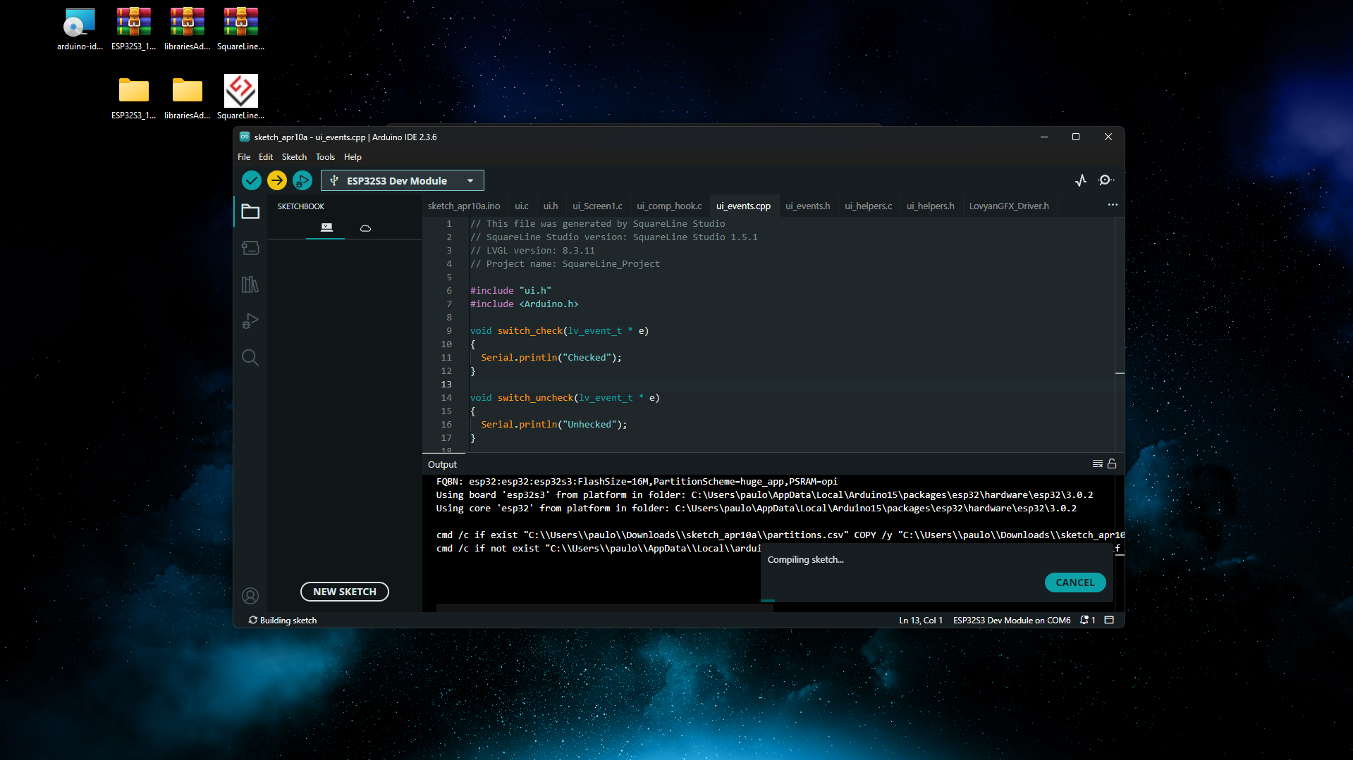
}On ‘ui_events.cpp’ add ‘Serial.println’ and then upload your code:
Once your code is uploaded, you should see your switch, and clicking it should toggle it and log a message to Serial:
And that’s it, you are now ready to make beautiful UIs for your CrowPanel Advance. You can check our review on it in this article, and if you want to, you can buy one at Elecrow’s store.
Thanks for reading, and stay tuned for more tech insights and tutorials. Until next time, and keep exploring the world of tech!