
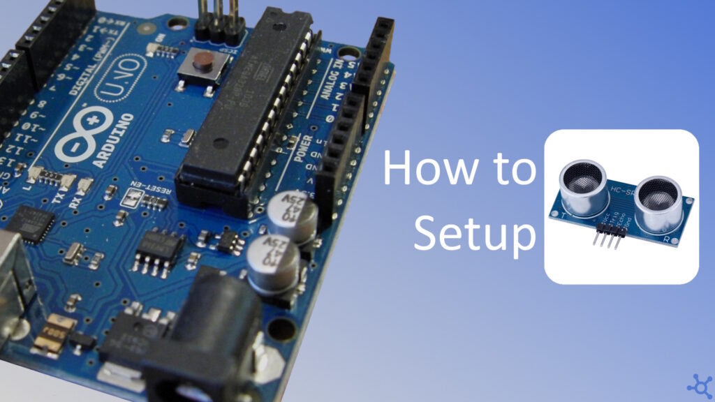
Ditching libraries and working directly with hardware can be a rewarding way to deepen your understanding of microcontrollers. In this guide, we’ll explore how to interface the HC-SR04 ultrasonic distance sensor with an Arduino Nano using baremetal programming, no external libraries, just pure register-level control.
If you are a usual reader of our baremetal tutorials we made a small library to help you get started with Pins and UART control. If you don’t care about that, you will have a link to jump to the part of the tutorial where we get the sensor working only with the main file after setting up your workspace.
To follow this article you only need a HC-SR04 distance sensor, an Arduino Nano and a computer with Ubuntu (VSCode is optional but recommended).
To code for the Arduino without the IDE, we will need some libraries. Go to your terminal and install the following AVR packages:
sudo apt install avr-libc avrdude binutils-avr gcc-avr build-essential
With those packages installed, create a folder for your project with the following structure:
projectfolder
├── Makefile
├── .vscode
│   └── c_cpp_properties.json
└── src
    └── main.cpp
Let’s start with the file inside ‘.vscode’, this file is usefull for those of you who like VSCode’s intellisense. This file will tell VSCode where the libraries header files are located at. Create the ‘.vscode’ folder with a file named ‘c_cpp_properties.json’ and, in it, paste the following json:
{
    "configurations": [
        {
            "name": "AVR",
            "includePath": [
                "${workspaceFolder}/**",
                "/usr/lib/avr/include/**"
            ],
            "defines": [
                "__AVR_ATmega328P__"
            ],
            "compilerPath": "/usr/bin/avr-gcc",
            "cStandard": "c11",
            "cppStandard": "gnu++11",
            "intelliSenseMode": "linux-gcc-x64"
        }
    ],
    "version": 4
}
Now we need a Makefile, this file will let us compile and upload our code to the Arduino by running commands like ‘make build’ and ‘make upload’:
# arduino nano
ARDUINO_PORT=/dev/ttyUSB0
ARDUINO_BAUD=115200
ARDUINO_F_CPU=16000000UL
ARDUINO_MMCU=atmega328p # atmega2560
ARDUINO_PROGRAMMER_ID=arduino # wiring

# ====================================================================================================
# directories
DIR_SRC=src
DIR_OUT=out
OUT_NAME=program

# ====================================================================================================
# files
SOURCES := $(shell find $(DIR_SRC) -name '*.cpp')

ARDUINO_ELF := $(DIR_OUT)/$(OUT_NAME)_arduino.elf
ARDUINO_HEX := $(DIR_OUT)/$(OUT_NAME)_arduino.hex

ARDUINO_OBJECTS := $(patsubst $(DIR_SRC)/%.cpp, $(DIR_OUT)/arduino/%.o, $(SOURCES))

# ====================================================================================================
# compiler flags
ARDUINO_CC= avr-gcc
ARDUINO_OCP= avr-objcopy
ARDUINO_UPL= sudo avrdude
ARDUINO_CC_FLAGS= -Os -Wall -DF_CPU=$(ARDUINO_F_CPU) -mmcu=$(ARDUINO_MMCU)
ARDUINO_CC_HEADERS=

# ====================================================================================================
# functions
.PHONY: build, upload, clean

# Compile for arduino
build: $(ARDUINO_HEX)
	$()

# Upload code to arduino
upload:
	$(ARDUINO_UPL) -V -c $(ARDUINO_PROGRAMMER_ID) -p $(ARDUINO_MMCU) -P $(ARDUINO_PORT) -b $(ARDUINO_BAUD) -D -U flash:w:$(ARDUINO_HEX):i

# Remove out folder
clean:
	rm -rf $(DIR_OUT)

# ====================================================================================================
# compile
$(DIR_OUT)/arduino/%.o: $(DIR_SRC)/%.cpp
	mkdir -p $(dir $@)
	$(ARDUINO_CC) $(ARDUINO_CC_FLAGS) -c -o $@ $<

$(ARDUINO_ELF): $(ARDUINO_OBJECTS)
	$(ARDUINO_CC) $(ARDUINO_CC_FLAGS) -o $@ $(ARDUINO_OBJECTS)

$(ARDUINO_HEX): $(ARDUINO_ELF)
	$(ARDUINO_OCP) $(ARDUINO_ELF) -O ihex $(ARDUINO_HEX)
Now that we have everything ready to code, let’s make our Arduino’s built in LED blink to test everything we have done until now. Keep in mind that this code is for the Arduino Nano and you might need to change the registers while using another one.
In this code we start by importing both ‘avr/io’ and ‘util/delay’, these two files contain everything we will need for this small test. In the main function we start by setting the ‘PB5’ bit in the ‘DDRB’ register, this sets pin D13 (connected to the LED) as output, then we create an infinite while loop where we turn on the LED by setting ‘PB5’ in the ‘PORTB’ register, wait a little, clear the bit to turn off the LED and finally wait a little more.
#include <avr/io.h>     // Used for registers and pins
#include <util/delay.h> // Used for _delay_ms

int main()
{
    DDRB |= _BV(PB5); // Set LED Pin as output

    while (1) // Loop forever
    {
        PORTB |= _BV(PB5); // Set pin as HIGH
        _delay_ms(100); // 100 ms LED On
        PORTB &= ~_BV(PB5); // Set pin as LOW
        _delay_ms(900); // 900 ms LED Off
    }
    return 0;
}
To compile and upload your code run:
make build
make upload
If you want to get your sensor working as fast as possible all inside the main file click here to jump to that part of the article. If instead, you want to make your code modular and easier to use in future projects, continue reading.
With all the Baremetal Arduino tutorials we write, one thing that is common in almost every single one of them is that we use pins and UART, because of that, I made a small ‘library’ that handles UART and pin modes and levels as well as adds the names of the pins like in Arduino (Ex: you can access pin D13 by writting D13, SPI_SCK or LED_BUILTIN).
Inside the ‘src’ directory, create a folder named ‘tavr’, that folder will have the following structure:
tavr
├── nano
│   ├── pins.cpp
│   ├── pins.h
│   ├── uart.cpp
│   └── uart.h
├── mega
│   └── # files for mega
├── uno
│   └── # files for uno
├── utils
│   ├── ringbuf.cpp
│   └── ringbuf.h
├── pins.h
└── uart.hThe first things we will create are two virtual classes, ‘tavr/pins.h’ and ‘tavr/uart.h’, these files will be like the blueprint for the micro controller specific implementation. Lets start with ‘pins.h’.
This header file will have a class and two enums. The first enum is the modes that the pin can be in, the second one is the state of the pin, or it’s level, which can either be high or low. The ‘TPin’ class has four public virtual methods, one for changing the pin mode, one for reading the pin state and the other two to set it’s state, one using the enum and the other using an integer or bool:
#ifndef _tavr_pins_h_
#define _tavr_pins_h_

#include <inttypes.h>

enum EPinMode : uint8_t
{
    INPUT = 0,
    OUTPUT = 1,
    INPUT_PULLUP = 2,
    INPUT_PULLDOWN = 3
};

enum EPinLevel : uint8_t
{
    LOW = 0,
    HIGH = 1
};

class TPin
{
    public:
    virtual void mode(EPinMode m) = 0;
    virtual void set(EPinLevel level) = 0;
    virtual void set(uint8_t level) = 0;
    virtual uint8_t read() = 0;
};

#endif // _pins_h_
Now go to the ‘nano’ folder inside ‘tavr’ and create another header file named ‘pins.h’ and a cpp file named ‘pins.cpp’.
The ‘pins.h’ inside this folder will be the implementation specific to the Arduino Nano. This file will have a class that is a child of ‘TPin’ and will override it’s four virtual methods but, besides that, it will also have four private variables, three registers and a bit, this is all the information we need to control the pins. Below the class we also create global variables for each of the pins to make it easier to use in our code.
#ifndef _tavr_nano_pins_h_
#define _tavr_nano_pins_h_

#include <avr/io.h>
#include "../pins.h"

class TPin_Nano : public TPin
{
    private:
    volatile uint8_t* ddr;
    volatile uint8_t* port;
    volatile uint8_t* pin;
    uint8_t bit;

    public:
    TPin_Nano(volatile uint8_t* ddr, volatile uint8_t* port, volatile uint8_t* pin, uint8_t bit);

    void mode(EPinMode mode) override;
    void set(EPinLevel v) override;
    void set(uint8_t v) override;
    uint8_t read() override;
};

#define LED_BUILTIN D13
#define PIN_OC2A D10

extern TPin_Nano D2;
extern TPin_Nano D3;
extern TPin_Nano D4;
extern TPin_Nano D5;
extern TPin_Nano D6;
extern TPin_Nano D7;
extern TPin_Nano D8;
extern TPin_Nano D9;
extern TPin_Nano D10;
extern TPin_Nano D11;
extern TPin_Nano D12;
extern TPin_Nano D13;
extern TPin_Nano D14;
extern TPin_Nano D15;
extern TPin_Nano D16;
extern TPin_Nano D17;
extern TPin_Nano D18;
extern TPin_Nano D19;

#define A0 D14
#define A1 D15
#define A2 D16
#define A3 D17
#define A4 D18
#define A5 D19

#define LED_BUILTIN D13

#define SPI_SCK D13
#define SPI_MISO D12
#define SPI_MOSI D11
#define SPI_CS D10

#define I2C_SCL A5
#define I2C_SDA A4

#define P_INT0 D2
#define P_INT1 D3

#endif // _tavr_nano_pins_h_
The ‘pins.cpp’ file is very simple, we start by creating the constructor that simply assigns the variables, then the ‘mode’ function sets the pins as either output or input (in case of input pullup it also needs to set the pin as high), the set functions either set or clear the bit in ‘PORTx’ turning the pin high or low and finally the read function reads from ‘PINx’ if the pin is set as input and reads from ‘PORTx’ if the pin is set as output.
Below the functions we also need to assign the global variables created in the header file.
#include "pins.h"

TPin_Nano::TPin_Nano(volatile uint8_t* ddr, volatile uint8_t* port, volatile uint8_t* pin, uint8_t bit) :
            ddr(ddr), port(port), pin(pin), bit(bit) {}

void TPin_Nano::mode(EPinMode mode)
{
    switch (mode)
    {
        case EPinMode::OUTPUT: *(this->ddr) |= _BV(this->bit); return;
        case EPinMode::INPUT_PULLUP:
            *(this->ddr) &= ~_BV(this->bit);
            *(this->port) |= _BV(this->bit);
            return;
        case EPinMode::INPUT:
        case EPinMode::INPUT_PULLDOWN:
        default:
            *(this->ddr) &= ~_BV(this->bit);
            *(this->port) &= ~_BV(this->bit);
            return;
    }
}

void TPin_Nano::set(EPinLevel level)
{
    switch (level)
    {
        case EPinLevel::HIGH: *(this->port) |= _BV(this->bit); return;
        case EPinLevel::LOW:
        default:
            *(this->port) &= ~_BV(this->bit);
            return;
    }
}

void TPin_Nano::set(uint8_t level)
{
    if (level)
        *(this->port) |= _BV(this->bit);
    else
        *(this->port) &= ~_BV(this->bit);
}

uint8_t TPin_Nano::read()
{
    if (*(this->ddr) & _BV(this->bit))
        return (*(this->port) & _BV(this->bit)) ? 1 : 0;
    else
        return (*(this->pin) & _BV(this->bit)) ? 1 : 0;
}

TPin_Nano D2  = TPin_Nano(&DDRD, &PORTD, &PIND, PD2);
TPin_Nano D3  = TPin_Nano(&DDRD, &PORTD, &PIND, PD3);
TPin_Nano D4  = TPin_Nano(&DDRD, &PORTD, &PIND, PD4);
TPin_Nano D5  = TPin_Nano(&DDRD, &PORTD, &PIND, PD5);
TPin_Nano D6  = TPin_Nano(&DDRD, &PORTD, &PIND, PD6);
TPin_Nano D7  = TPin_Nano(&DDRD, &PORTD, &PIND, PD7);
TPin_Nano D8  = TPin_Nano(&DDRB, &PORTB, &PINB, PB0);
TPin_Nano D9  = TPin_Nano(&DDRB, &PORTB, &PINB, PB1);
TPin_Nano D10 = TPin_Nano(&DDRB, &PORTB, &PINB, PB2);
TPin_Nano D11 = TPin_Nano(&DDRB, &PORTB, &PINB, PB3);
TPin_Nano D12 = TPin_Nano(&DDRB, &PORTB, &PINB, PB4);
TPin_Nano D13 = TPin_Nano(&DDRB, &PORTB, &PINB, PB5);
TPin_Nano D14 = TPin_Nano(&DDRC, &PORTC, &PINC, PC0);
TPin_Nano D15 = TPin_Nano(&DDRC, &PORTC, &PINC, PC1);
TPin_Nano D16 = TPin_Nano(&DDRC, &PORTC, &PINC, PC2);
TPin_Nano D17 = TPin_Nano(&DDRC, &PORTC, &PINC, PC3);
TPin_Nano D18 = TPin_Nano(&DDRC, &PORTC, &PINC, PC4);
TPin_Nano D19 = TPin_Nano(&DDRC, &PORTC, &PINC, PC5);
With some small changes to our main file, we can now use our ‘pins.h’ file to control the LED state:
#include <avr/io.h>
#include <util/delay.h>

#include "tavr/nano/pins.h"

int main()
{
    LED_BUILTIN.mode(EPinMode::OUTPUT);

    while (1)
    {
        LED_BUILTIN.set(EPinLevel::HIGH);
        _delay_ms(100);
        LED_BUILTIN.set(EPinLevel::LOW);
        _delay_ms(900);
    }
    return 0;
}
To compile and upload your code run:
make build
make uploadInside ‘tavr/utils’ create a file named ‘ringbuf.h’, this will be a data structure that will help us once we start implementing the UART.
This data structure will have a pointer to an array, the size of the array and then two indices, head and tail, besides that, it will also have four functions, one to add data, one to remove, one to calculate the length and a final one that marks the buffer as empty:
#ifndef _tavr_utils_ringbuf_h_
#define _tavr_utils_ringbuf_h_

#include <inttypes.h>

/* Buffer with 'no end' as long as you
 * read it faster than you write to it */
class TRingbuf
{
    uint8_t* data;   /* internal buffer */
    uint16_t maxlen; /* internal buf len */
    uint16_t head;   /* write pointer */
    uint16_t tail;   /* read pointer */

    public:
    /* @brief Creates a ring buffer with the given array and size
    * @param internal_buf internal buffer
    * @param maxlen internal buffer size */
    TRingbuf(uint8_t* internal_buf, uint16_t maxlen);

    /* @brief Saves a value to the buffer
    * @param val value to store in the buffer */
    uint8_t push(uint8_t val);

    /* @brief Reads a value from the buffer
    * @param out pointer to store the value read */
    uint8_t pop(uint8_t* out);

    /* @brief Calculates the ammount of data in the buffer */
    uint16_t length();

    /* @brief Empties the buffer. Sets head and tail to 0 */
    void clear();
};

#endif
On the ‘ringbuf.cpp’ file, implement the constructor by simply assigning the pointer to the buffer and it’s size and settings both head and tail to zero. The ‘push’ function will check if the buffer as space and if it does, it will add the data to it. The ‘pop’ function checks if the buffer has data in it and if it does, returns it to the ‘out’ variables in it’s aguments. The ‘length’ function calculates the ammount of items inside the array and the clear function sets both the head and tail to zero:
#include "ringbuf.h"

TRingbuf::TRingbuf(uint8_t* internal_buf, uint16_t maxlen)
{
    this->data = internal_buf;
    this->maxlen = maxlen;
    this->head = 0;
    this->tail = 0;
}

uint8_t TRingbuf::push(uint8_t val)
{
    uint16_t n = this->head + 1; // next pos
    if (n >= this->maxlen) // reached end of buffer
        n = 0;
    if (n == this->tail) // buffer full
        return 0;
    this->data[this->head] = val; // save data
    this->head = n; // update head
    return 1;
}

uint8_t TRingbuf::pop(uint8_t* out)
{
    if (this->head == this->tail) // empty
        return 0;
    uint16_t n = this->tail + 1; // next pos
    if (n >= this->maxlen) // reached end of buffer
        n = 0;
    *out = this->data[this->tail]; // read data
    this->tail = n; // update tail pos
    return 1;
}

uint16_t TRingbuf::length()
{
    if (this->head == this->tail) // empty buf
        return 0;
    else if (this->tail < this->head) // tail behind head
        return (this->maxlen - this->head + this->tail);
    else return this->tail - this->head; // tail after head
}

void TRingbuf::clear()
{
    this->head = 0;
    this->tail = 0;
}
Now that we have the Ring Buffer data structure, lets create the virtual class for the UART. Create a file named ‘uart.h’ inside the ‘tavr’ folder, in it, create a class with virtual functions like, ‘read’, ‘send’ string, character and byte array and then a function to send an integer and one to send a new line (Either ‘\n‘ or ‘\r\n‘).
#ifndef _tavr_uart_h_
#define _tavr_uart_h_

#include <inttypes.h>

class TUart
{
    public:
    /* @brief Read a value from the uart
    * @param out pointer to store the value read */
    virtual uint8_t read(uint8_t* out) = 0;

    /* @brief Send a string via uart
    * @param str string to send */
    virtual void send(const char* str) = 0;

    /* @brief Send a string via uart
    * @param c char to send */
    virtual void send(uint8_t c) = 0;

    /* @brief Send bytes via uart
     * @param data data to send
     * @param len data size */
    virtual void send(const uint8_t* buf, uint16_t len) = 0;

    /* @brief Send a string via uart
    * @param v number to send */
    virtual void sendNumber(uint32_t n, uint16_t base) = 0;

    /* @brief Sends a new line char */
    virtual void newline() = 0;
};

#endif
Then we move onto ‘tavr/nano/uart.h’, in this file we create a class that inherits ‘TUart’ from ‘tavr/uart.h’, besides overriding the functions in the virtual class, we also need to add some variables, like the buffers, a flag to know if the Uart is currently sending anything and a static pointer to an instance of this class so that it can be accessed from the ISRs (interrupts), besides the variables we will also create a static function to get the current instance of this class and two non-static functions that will be called inside the ISRs:
#ifndef _tavr_nano_uart_h_
#define _tavr_nano_uart_h_

#include "../uart.h"
#include "../utils/ringbuf.h"

#ifndef UART_NANO_BUFSIZE
/* Buffer size of UARTs for the Arduino Mega (two buffers of this size are created) */
#define UART_NANO_BUFSIZE 128
#endif

class TUart_Nano : TUart
{
    private:
    uint8_t m_txflag; // true if the uart is currently sending
    uint8_t m_txbuf_[UART_NANO_BUFSIZE]; // send buffer (internal buffer for the ring buffer)
    uint8_t m_rxbuf_[UART_NANO_BUFSIZE]; // receive buffer (internal buffer for the ring buffer)
    TRingbuf m_txbuf; // send ringbuf
    TRingbuf m_rxbuf; // receive ringbuf
    static TUart_Nano* instance;

    public:
    TUart_Nano(uint32_t baud, uint8_t doubleSpeed = 1);

    /* @brief Read a value from the uart
    * @param out pointer to store the value read */
    uint8_t read(uint8_t* out) override;

    /* @brief Send a string via uart
    * @param str string to send */
    void send(const char* str) override;

    /* @brief Send a string via uart
    * @param c char to send */
    void send(uint8_t c) override;

    /* @brief Send bytes via uart
     * @param data data to send
     * @param len data size */
    void send(const uint8_t* buf, uint16_t len) override;

    /* @brief Send a string via uart
    * @param v number to send */
    void sendNumber(uint32_t n, uint16_t base) override;

    /* @brief Sends a new line char */
    void newline() override;


    static TUart_Nano* getUART();
    void isr_send();
    void isr_receive(uint8_t v);
};

#endif
In the cpp file, before implementing the functions we declared in the header file, we will also create some new ones, one of them being the ‘uart_ubrrn_from_baud’ function. This function takes a baudrate and whether it should use double speed and, using a table in the datasheet, returns the value for the ‘UBRRn’ register.
The next new function is ‘uart_init’ this function’s job is to enable the UART’s transmitter and receiver along with their interrupts, set the baudrate, double speed and to set the format as 8bit data and 2bit stop.
Finally the last helper function will be called ‘uart_str_fromint’ and it converts a 32bit unsigned integer into a string.
The constructor of the ‘TUart_Nano’ class will take the baud and double speed, intialize the ring buffers and tx flag, set the static instance to this class and then call ‘uart_init’.
The function ‘isr_send’ will check if there is any data to send, and if there is, write it to ‘UDR0’ while the ‘isr_receive’ function simply pushes the data received to the receive buffer.
The ‘read’ function tries to pop data from the receive buffer and the ‘send’ functions simply add data to the buffer and start sending data if nothing is being sent.
The instance static variable can be initialized to ‘nullptr’ and ‘getUART’ will return that static variable.
Finally, on the ISRs, get the UART instance and, if it isn’t null, call either ‘isr_send’ or ‘isr_receive’ inside that instance.
#include "uart.h"
#include <avr/io.h>
#include <avr/interrupt.h>

uint16_t uart_ubrrn_from_baud(uint32_t baud, uint8_t u2xn)
{
    if (u2xn) // If using double speed
    {
        switch (baud)
        {
            case    2400: return 832;
            case    4800: return 416;
            case    9600: return 207;
            case   14400: return 138;
            case   19200: return 103;
            case   28800: return 68;
            case   38400: return 51;
            case   57600: return 34;
            case   76800: return 25;
            case  115200: return 16;
            case  230400: return 8;
            case  250000: return 7;
            case  500000: return 3;
            case 1000000: return 1;
            default: return 16; // 115200
        }
    }
    switch (baud)
    {
        case    2400: return 416;
        case    4800: return 207;
        case    9600: return 103;
        case   14400: return 68;
        case   19200: return 51;
        case   28800: return 34;
        case   38400: return 25;
        case   57600: return 16;
        case   76800: return 12;
        case  115200: return 8;
        case  230400: return 3;
        case  250000: return 3;
        case  500000: return 1;
        case 1000000: return 0;
        default: return 8; // 115200
    }
}

void uart_init(uint32_t baud, uint8_t doubleSpeed)
{
    // set baud rate
    UBRR0 = uart_ubrrn_from_baud(baud, doubleSpeed);
    // enable receiver and transmitter
    UCSR0B |= _BV(RXEN0) | _BV(TXEN0);
    // enable interrupts
    UCSR0B |= _BV(RXCIE0) | _BV(TXCIE0);
    // double speed
    if (doubleSpeed)
        UCSR0A |= _BV(U2X0);
    // 8bit, 2bit stop
    UCSR0C |= _BV(USBS0) | _BV(UCSZ02);
}

uint16_t uart_str_fromint(char* buf, uint16_t maxlen, uint32_t v, uint32_t base)
{
    if (maxlen <= 1) // return if buffer has no space
        return 0;
    if (v == 0) // if number is 0, add 0 and the null char
    {
        buf[0] = '0'; // add 0
        buf[1] = '\0'; // add null char
        return 1;
    }
    char temp[11]; // 11 digits is the max an uint32 base 10 can have
    uint8_t i = 0;
    while (v > 0) // while the number is greater than 0
    {
        uint8_t digit = v % base; // get the digit
        temp[i++] = (digit < 10) ? (digit + '0') : (digit - 10 + 'A'); // add digit
        v /= base; // divide by base
    }
    uint8_t j = 0;
    while (i > 0 && j < maxlen - 1) // add string to buffer (reversed)
        buf[j++] = temp[--i];
    buf[j] = '\0'; // null char
    return j; // return size
}


TUart_Nano::TUart_Nano(uint32_t baud, uint8_t doubleSpeed) :
    m_txflag(0),
    m_txbuf(m_txbuf_, UART_NANO_BUFSIZE),
    m_rxbuf(m_rxbuf_, UART_NANO_BUFSIZE)
{
    this->instance = this;
    uart_init(baud, doubleSpeed);
}

void TUart_Nano::isr_send()
{
    uint8_t c;
    if (m_txbuf.pop(&c))
    {
        m_txflag = 1;
        UDR0 = c;
    }
    else m_txflag = 0;
}
void TUart_Nano::isr_receive(uint8_t v) { m_rxbuf.push(v); }


uint8_t TUart_Nano::read(uint8_t* out)  { return m_rxbuf.pop(out); }

void TUart_Nano::send(const char* str)
{
    while (*str != '\0')
        m_txbuf.push(*str++);
    if (!m_txflag)
        isr_send();
}
void TUart_Nano::send(uint8_t c)
{
    m_txbuf.push(c);
    if (!m_txflag)
        isr_send();
}
void TUart_Nano::send(const uint8_t* buf, uint16_t len)
{
    for (uint8_t i = 0; i < len; i++)
        m_txbuf.push(buf[i]);
    if (!m_txflag)
        isr_send();
}

void TUart_Nano::sendNumber(uint32_t n, uint16_t base)
{
    char buf[16];
    uart_str_fromint(buf, 15, n, base);
    send(buf);
}

void TUart_Nano::newline() { send("\r\n"); }


TUart_Nano* TUart_Nano::instance = nullptr;
TUart_Nano* TUart_Nano::getUART() { return instance; }

// ISR
// ========== ========== ========== ========== ========== ==========

ISR(USART_TX_vect)
{
    TUart_Nano* u = TUart_Nano::getUART();
    if (u) u->isr_send();
}

ISR(USART_RX_vect)
{
    TUart_Nano* u = TUart_Nano::getUART();
    if (u) u->isr_receive(UDR0);
}
With some small changes to our main file, we can now use our ‘pins.h’ file to control the LED state and ‘uart.h’ to send and receive data via UART:
#include <avr/io.h>
#include <avr/interrupt.h>
#include <util/delay.h>

#include "tavr/nano/pins.h"
#include "tavr/nano/uart.h"

int main()
{
    LED_BUILTIN.mode(EPinMode::OUTPUT);

    TUart_Nano uart(115200, 1);
    sei(); // Enable interrupts

    uart.send("Hello\n");

    while (1)
    {
        LED_BUILTIN.set(EPinLevel::HIGH);
        _delay_ms(100);
        LED_BUILTIN.set(EPinLevel::LOW);
        _delay_ms(900);

        uint8_t data; // Echo received
        if (uart.read(&data))
            uart.send(data);
    }
    return 0;
}
To compile and upload your code run:
make build
make uploadWith the ‘library’ to control the pins and uart, lets now make a driver for our distance sensor. Start by creating a file named ‘hc_sr04.h’ and, in it, create the class below. It should have two private variables that are the pointers to the pins we will use, a constructor where we pass in those pins and a function to make a measurement.
#ifndef _HC_SR04_h_
#define _HC_SR04_h_

#include "tavr/pins.h"

class HC_SR04
{
    TPin *trig, *echo;

    public:

    HC_SR04(TPin* trig, TPin* echo);
    float dist_cm();
};

#endif
On the ‘hc_sr04.cpp’ file, on the constructor, assign the pins and set the trigger as output and the echo as input. On the ‘dist_cm’ function we will send a 10 microsecond pulse in the ‘trig’ pin, then with the help of Timer1 (16bit precision vs 8bit of Timer0 and 2), we measure the time it takes the ‘echo’ to go from high to low, finally we calculate the distance in centimeters and return it.
In the code below I also disabled interrupts by calling ‘cli’ while we are measuring to avoid inacuracies caused by, for example, a uart interrupt. At the end of the measurement we need to call ‘sei’ to re-enable the interrupts.
#include "hc_sr04.h"

#include <avr/io.h>
#include <avr/interrupt.h>
#include <util/delay.h>

HC_SR04::HC_SR04(TPin* trig, TPin* echo)
{
    // Save pointer to pins
    this->trig = trig;
    this->echo = echo;
    // Set pins as output and input
    this->trig->mode(EPinMode::OUTPUT);
    this->echo->mode(EPinMode::INPUT);
}

float HC_SR04::dist_cm()
{
    // Send trigger
    trig->set(0); // Set trigger as low
    _delay_us(2); // Wait 2 micro seconds
    cli(); // Disable interrupts
    trig->set(1); // Set trigger as high
    _delay_us(10); // Wait 10 micro seconds
    trig->set(0); // Set trigger as low

    TCNT1 = 0;  // Reset Timer1
    TCCR1B = (1 << CS11); // Start Timer1 with prescaler 8
    while (!echo->read()); // Wait for Echo HIGH
    TCNT1 = 0; // Reset Timer1 again
    while (echo->read()); // Wait for Echo LOW
    TCCR1B = 0; // Stop Timer1
    sei(); // Enable interrupts

    return ((float)TCNT1 / 2.0) * 0.0343 / 2.0;
}
On ‘main.cpp’, include the headers for the pins, uart and the HC-SR04 sensor and on the main function, set the led pin as output, create the UART and HC-SR04 sensor, enable interrupts and send a hello message, on an infinite loop, turn the led on, send the reading via uart, turn the led off and wait some 500 milliseconds.
#include <avr/io.h>
#include <avr/interrupt.h>
#include <util/delay.h>

#include "tavr/nano/pins.h"
#include "tavr/nano/uart.h"
#include "hc_sr04.h"

int main()
{
    // Set led pin as output
    LED_BUILTIN.mode(EPinMode::OUTPUT);

    // Create UART and distance sensor
    TUart_Nano uart(115200);
    HC_SR04 sensor(&D4, &D5);
    // Enable interrupts
    sei();

    // Send hello
    uart.send("Hello\r\n");

    // Loop forever
    while (1)
    {
        // Turn led on
        LED_BUILTIN.set(EPinLevel::HIGH);
        // Send measurement via uart
        uart.send("Distance: ");
        uart.sendNumber((uint32_t)(sensor.dist_cm()), 10);
        uart.newline();

        // Turn led off and wait 500ms
        LED_BUILTIN.set(EPinLevel::LOW);
        _delay_ms(500);
    }
    return 0;
}
And that’s it, you now have a driver for your HC-SR04 distance sensor as well as a base ‘library’ for your future projects. If you don’t want to use the pins and UART classes from ‘TAVR’ you can continue reading as we will implement the same functionality all in the ‘main.cpp’ file, no external libraries or files.
All of the following code blocks will be on the same ‘main.cpp’ file. If you want to download the complete main file, you can get it here. You can also test this code out in the Wokwi emulator.
Start by including ‘avr/io’ and ‘util/delay’:
#include <avr/io.h>
#include <util/delay.h>
Then define which pins we will use, in this case, PD2 is D2 and PD3 is D3:
#define TRIG_PIN PD2
#define ECHO_PIN PD3
To be able to send messages via UART, we will need the following three functions: ‘uart_init’ which will initialize the uart transmitter at a baudrate of 115200 and with 8bits of data, ‘uart_tx’ will wait until the send buffer is clear and then write a character to it and finally the ‘uart_print’ function will call ‘uart_tx’ for every character in the string:
/* Intialize the uart */
void uart_init(void)
{
    UBRR0H = 0;
    UBRR0L = 16;  // Baud rate 115200 at 16MHz
    UCSR0B = (1 << TXEN0);  // Enable TX
    UCSR0C = (1 << UCSZ01) | (1 << UCSZ00);  // 8-bit data
}

/* Send character via uart */
void uart_tx(char c)
{
    while (!(UCSR0A & (1 << UDRE0)));  // Wait for buffer
    UDR0 = c; // Send character
}

/* Send string via uart */
void uart_print(const char* str)
{
    while (*str)
        uart_tx(*str++);
}
Moving on to the ‘measure’ function, this will be the function that actually communicates with the sensor. The first thing we need to do is to set the trigger pin as high for ten microseconds and then turn it off, then enable the Timer1 and wait for the echo pin to become high, reset the counter and wait for it to become low, stop the timer and then calculate the distance in centimeters from the time it took the pin to go from high to low:
/* Measure distance with sensor */
float measure()
{
    PORTD |= (1 << TRIG_PIN);
    _delay_us(10);
    PORTD &= ~(1 << TRIG_PIN);

    TCNT1 = 0;  // Reset Timer1
    TCCR1B = (1 << CS11);  // Start Timer1 with prescaler 8

    while (!(PIND & (1 << ECHO_PIN)));  // Wait for Echo HIGH
    TCNT1 = 0;  // Reset Timer1 again
    while (PIND & (1 << ECHO_PIN));  // Wait for Echo LOW

    TCCR1B = 0;  // Stop Timer1
    return ((float)TCNT1 / 2.0) * 0.0343 / 2.0;;
}
On ‘main’, create a small buffer where we can write our messages, initialize UART, set the ‘trig’ pin as output and ‘echo’ as input, in an infinite loop, take a measurement, use ‘snprintf’ to print a message with the measurement, send the message and wait 500 milliseconds:
int main()
{
    char buf[32]; // Buffer for the message to send
    uart_init(); // Initialize uart

    DDRD |= (1 << TRIG_PIN);  // Trig as output
    DDRD &= ~(1 << ECHO_PIN); // Echo as input

    // Loop forever
    while (1)
    {
        // Get measurement
        float cm = measure();

        // Convert to string
        sprintf(buf, "Dist: %d cm\r\n", (uint16_t)cm);
        // Send message via uart
        uart_print(buf);

        // Wait 500ms
        _delay_ms(500);
    }
}
And that’s it. Thanks for reading and stay tuned for more tech insights and tutorials. Until next time, keep exploring the world of tech!