
Retro gaming enthusiasts often look back fondly at the CHIP-8 virtual machine, which powered early homebrew games in the 1970s. In this tutorial, we’ll create a CHIP-8 emulator console using an ESP32 microcontroller, a keypad, an LCD, and an SD card reader. By the end, you’ll have a fully functional handheld console that can run classic 8-bit games.
If you want a deeper analysis or to run this emulator on a different platform, check out below all the previous Chip8 tutorial articles we wrote:

For this tutorial, we will use more components than what it is usually required for our other tutorials. Here is a list of everything we will need:
- 1x Esp32 (read review here)
- 1x 4 by 4 Keypad
- 1x ST7735 Display
- 1x SD Card reader + Card
- 4x 5k Resistors (or similar)
- 1x Buzzer (optional)
- Some wires
Other materials will be needed when we build the case for the console, you can skip to the build section to check the materials.
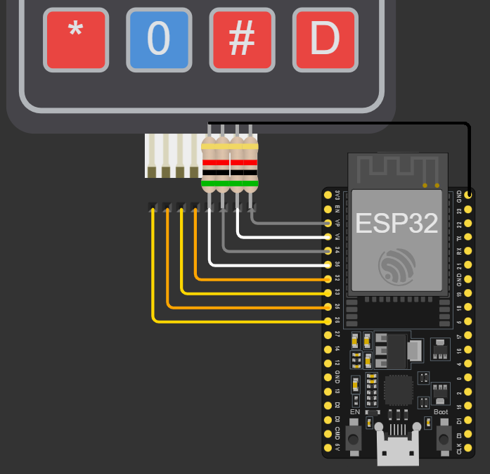
This is how our project will be wired, but to make it easier to understand, we will look at it component by component below:
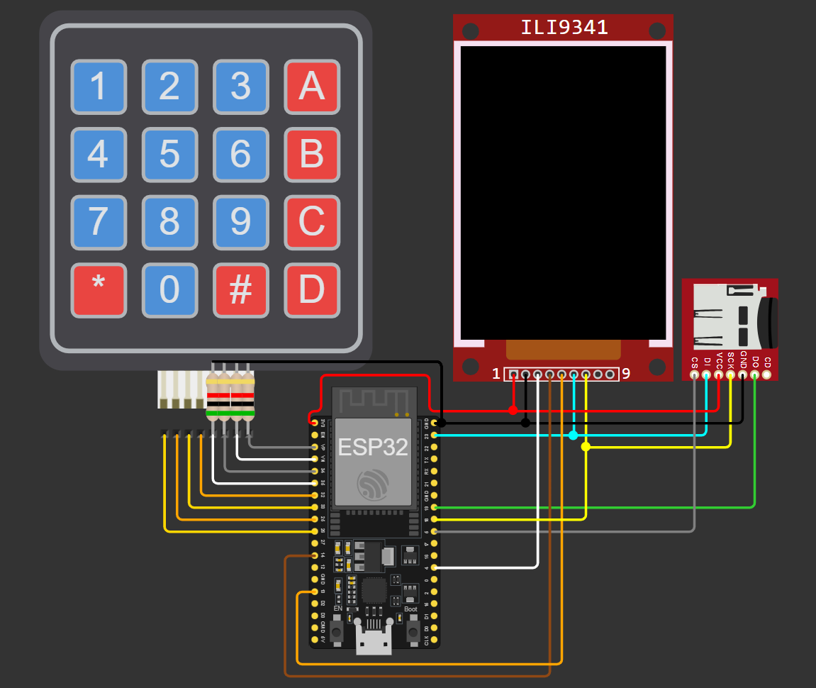
Let’s start with the keyboard. We will connect the first four pins to 26, 25, 33 and 32 on our Esp, these will be output pins. Then we connect the other four to 36, 34, VN and VP, these will be our input pins. For the keyboard to work, though, we will also need to add some pull down resistors. We do that by connecting a resistor to each one of the input pins and then to ground:
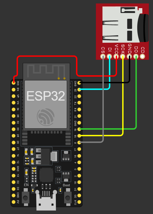
Now we move onto the SD Card Reader. For this module we will use all the SPI pins, ground, 3.3V and one extra pin to be Chip Select. We connect, 3.3V to VCC, GND to GND, pin 23 to DI, pin 19 to DO, pin 18 to SCK and finally, pin 5 to CS:
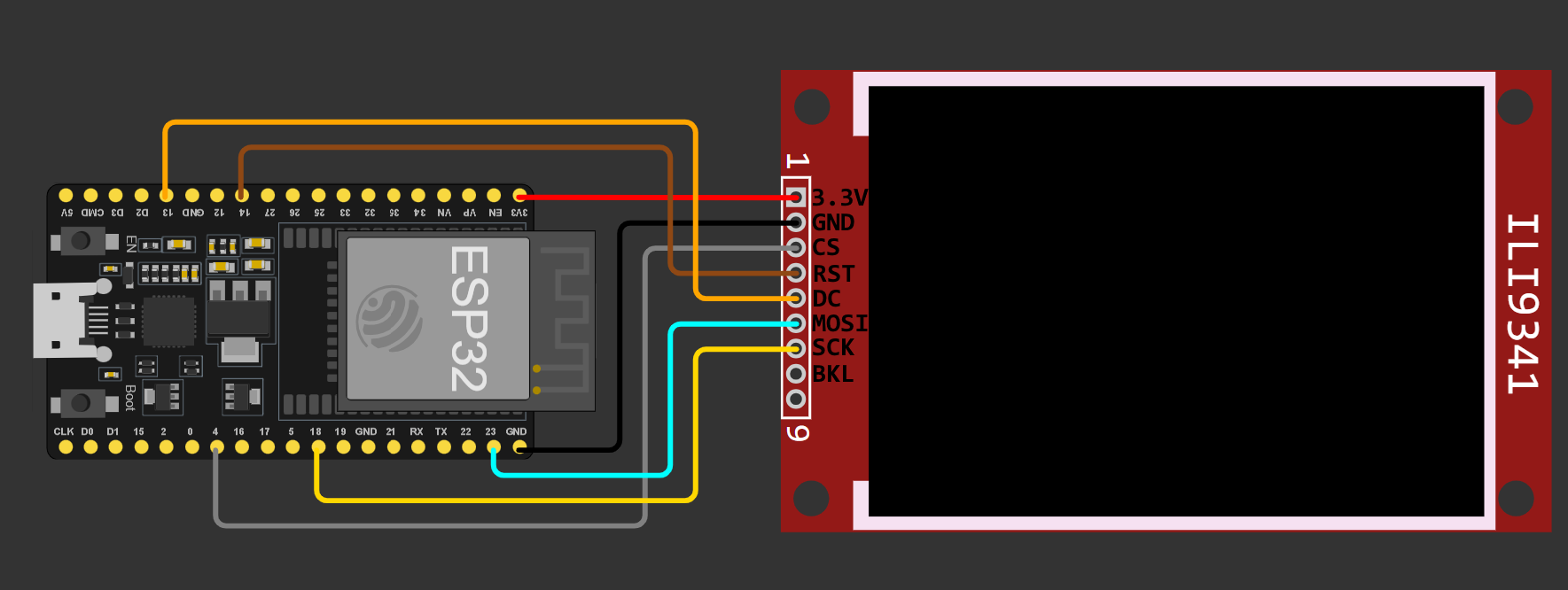
For the display, connect 3.3V to 3.3V, GND to GND, pin 4 to CS, pin 14 to RST, pin 13 to DC, pin 23 to MOSI and pin 18 to SCK. If your display has a backlight pin, either leave it disconnected, or plug it in to 3.3V (only if the display does not light up), also, if your display has a MISO pin, leave it unplugged:
Now we need to put everything together, in WokWi, you can use junctions, but in real life, you will either need to use a breadboard, or you can create a junction with DuPont headers.
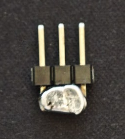
Take a 3 pin header, use a wire to connect all 3 pins and then solder it all together. To avoid shorts, you can also add a shrink sleeve around the solder:
If you don’t want to add a buzzer, you will need 3x 3 pin headers and 1x 4 pin header, the 4 pin one will be used to connect the grounds (Esp, Display, Card Reader, and the Keypad’s input pins) and the other 3 will be used for 3.3V, SPI’s MOSI and SPI’s SCK (Esp, Display, and Card Reader).
If you want to use the buzzer you will instead need, 1x 5 pin for the grounds, 1x 4 pin for 3.3V and 2x 3 pin for MOSI and SCK.
If you don’t want to test the hardware before assembling, you can also just skip to the build, where we will solder some pins to a proto board.
2 - Setup Workspace
Let’s now move to the code. We will need VS Code with the Platform IO extension. Create a folder for your project and, in it, create a file named ‘platformio.ini’ with the following contents:
mkdir esp32-c8console
cd esp32-c8console
nano platformio.ini
[env:nodemcu-32s]
platform = espressif32
board = nodemcu-32s
framework = arduino
lib_deps = adafruit/Adafruit ST7735 and ST7789 Library@^1.11.0We will use the Adafruit ST7735 Library to drive our display. After saving the file, either reload the window or close and re-open VS Code.
Then create a folder named ‘src’ with two folders inside, one named ‘chip8’ and another named ‘modules’. Besides the folders, create also a file named ‘pins.h’ with the following contents:
#ifndef _pins_h_
#define _pins_h_

#include <Arduino.h>

#define SD_CS GPIO_NUM_5
#define DISP_CS GPIO_NUM_4
#define DISP_RST GPIO_NUM_14
#define DISP_DC GPIO_NUM_13

#endif
Here is how your project directory should look like:
📂 esp32-c8console
├── 📄 platformio.ini
└── 📂 src
    ├── 📂 chip8
    ├── 📂 modules
    ├── 📄 main.cpp
└── 📄 pins.hBecause this emulator project was always meant to be portable, we will have 3 distinct ‘parts’. The first one being the interfaces, these are small header files that tell us what the platform specific modules will need to implement for the emulator to work.
These interfaces will be placed inside the chip8 folder. Here is how the folder should look like after adding the files:
📂 chip8
├── 📄 idisplay.h
├── 📄 ikeyboard.h
├── 📄 ilogger.h
├── 📄 irandom.h
├── 📄 isound.h
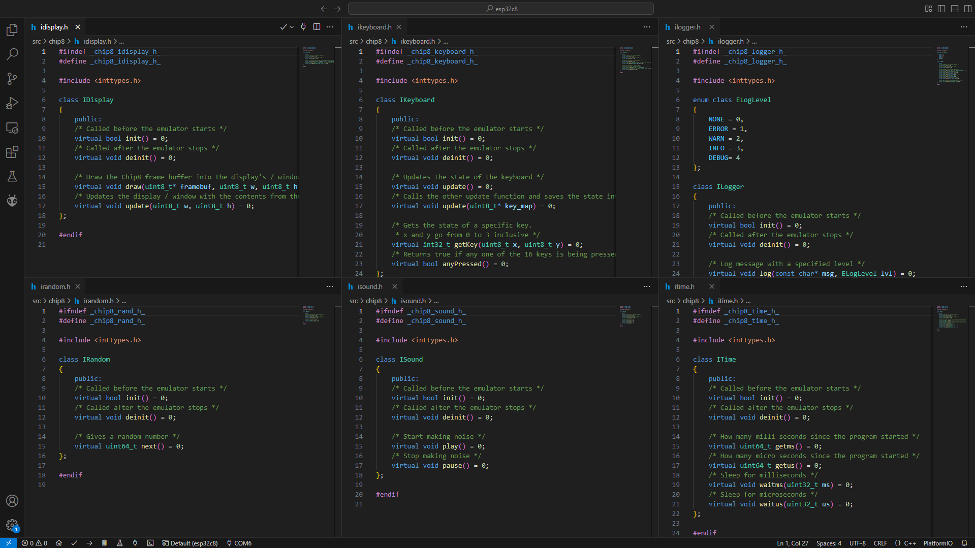
└── 📄 itime.hBelow you can get all the interfaces we will need to make the emulator run:
idisplay.h
Let’s start with the display interface, this one has 4 functions, the first two, ‘init’ and ‘deinit’ will be present in all modules, and are called automatically by the emulator when it starts up. The ‘draw’ function takes in three arguments, the frame buffer from the Chip8 emulator and its size, this function will draw the Chip8’s frame buffer in the platform specific frame buffer. Finally, the ‘update’ function sends the frame buffer to the target display or window.
#ifndef _chip8_idisplay_h_
#define _chip8_idisplay_h_

#include <inttypes.h>

class IDisplay
{
    public:
    /* Called before the emulator starts */
    virtual bool init() = 0;
    /* Called after the emulator stops */
    virtual void deinit() = 0;

    /* Draw the Chip8 frame buffer into the display's / window's buffer */
    virtual void draw(uint8_t* framebuf, uint8_t w, uint8_t h) = 0;
    /* Updates the display / window with the contents from the frame buffer */
    virtual void update(uint8_t w, uint8_t h) = 0;
};

#endif
ikeyboard.h
The keyboard interface was the one that suffered the most changes. This interface originally only had ‘init’, ‘deinit’ and ‘update’ with a key map as argument. As you can see below, it was changed, and now it gives us access to how much time a key is being held and when it was ‘just released’. These changes will help us a lot later when we write the menu UI.
#ifndef _chip8_keyboard_h_
#define _chip8_keyboard_h_

#include <inttypes.h>

class IKeyboard
{
    public:
    /* Called before the emulator starts */
    virtual bool init() = 0;
    /* Called after the emulator stops */
    virtual void deinit() = 0;

    /* Updates the state of the keyboard */
    virtual void update() = 0;
    /* Calls the other update function and saves the state into key_map */
    virtual void update(uint8_t* key_map) = 0;

    /* Gets the state of a specific key.
     * x and y go from 0 to 3 inclusive */
    virtual int32_t getKey(uint8_t x, uint8_t y) = 0;
    /* Returns true if any one of the 16 keys is being pressed */
    virtual bool anyPressed() = 0;
};

#endif
ilogger.h
The next module is the logging module. The job of this one is to log error and other types of messages to the console (in our case, the Serial Monitor). This module has a couple of functions, but they are mostly the same, one sets the log level and the others log at a specific level.
#ifndef _chip8_logger_h_
#define _chip8_logger_h_

#include <inttypes.h>

enum class ELogLevel
{
    NONE = 0,
    ERROR = 1,
    WARN = 2,
    INFO = 3,
    DEBUG= 4
};

class ILogger
{
    public:
    /* Called before the emulator starts */
    virtual bool init() = 0;
    /* Called after the emulator stops */
    virtual void deinit() = 0;

    /* Log message with a specified level */
    virtual void log(const char* msg, ELogLevel lvl) = 0;
    /* Log message with the debug level */
    virtual void log(const char* msg) = 0;
    /* Log message with the info level */
    virtual void info(const char* msg) = 0;
    /* Log message with the warn level */
    virtual void warn(const char* msg) = 0;
    /* Log message with the error level */
    virtual void error(const char* msg) = 0;

    /* Sets the log level = maximum level to log */
    virtual void setLogLvl(ELogLevel lvl) = 0;
};

#endif
irandom.h
The random module’s job is simply to give us random numbers. On the Esp32, it calls the ‘esp_random’ function.
#ifndef _chip8_rand_h_
#define _chip8_rand_h_

#include <inttypes.h>

class IRandom
{
    public:
    /* Called before the emulator starts */
    virtual bool init() = 0;
    /* Called after the emulator stops */
    virtual void deinit() = 0;

    /* Gives a random number */
    virtual uint64_t next() = 0;
};

#endif
isound.h
The sound module is also very simple, it has two functions, one to make the buzzer play a sound and another to make it stop. If you don’t have a buzzer connected, it will make your built-in LED blink (pin 2).
#ifndef _chip8_sound_h_
#define _chip8_sound_h_

#include <inttypes.h>

class ISound
{
    public:
    /* Called before the emulator starts */
    virtual bool init() = 0;
    /* Called after the emulator stops */
    virtual void deinit() = 0;

    /* Start making noise */
    virtual void play() = 0;
    /* Stop making noise */
    virtual void pause() = 0;
};

#endif
itime.h
The time module will have two jobs. The first one will be to give us the current time, we will use this to calculate how much time the emulator takes to tick. The second job is to make the thread sleep, we will use this to wait for the required amount to make the emulator run at the target clock speed.
#ifndef _chip8_time_h_
#define _chip8_time_h_

#include <inttypes.h>

class ITime
{
    public:
    /* Called before the emulator starts */
    virtual bool init() = 0;
    /* Called after the emulator stops */
    virtual void deinit() = 0;

    /* How many milli seconds since the program started */
    virtual uint64_t getms() = 0;
    /* How many micro seconds since the program started */
    virtual uint64_t getus() = 0;
    /* Sleep for milliseconds */
    virtual void waitms(uint32_t ms) = 0;
    /* Sleep for microseconds */
    virtual void waitus(uint32_t us) = 0;
};

#endif
Before proceeding, make sure you have the following six files inside the chip8 directory:
Now we need to implement the platform specific modules. We will start with the logger module, as it is the most useful of them all for debugging. In the modules’ folder create two files, ‘logger.h’ and ‘logger.cpp’, you can find the contents of the files below:
logger.h
The header file defines the ‘EspLogger’ class, which inherits from the ‘ILogger’ interface. Besides the overrides, it also contains a private variable that keeps track of the log level and two constructors to set that log level.
#ifndef _logger_h_
#define _logger_h_

#include <inttypes.h>
#include "chip8/ilogger.h"

class EspLogger: public ILogger
{
    ELogLevel _lvl;

    public:
    EspLogger(ELogLevel lvl): _lvl(lvl) {}
    EspLogger(): EspLogger(ELogLevel::DEBUG) {}

    bool init() override;
    void deinit() override;

    void log(const char* msg, ELogLevel lvl) override;
    void log(const char* msg) override;
    void info(const char* msg) override;
    void warn(const char* msg) override;
    void error(const char* msg) override;
    void setLogLvl(ELogLevel lvl) override;
};

#endif
logger.cpp
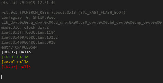
The CPP file implements the methods of ‘EspLogger’. The ‘init’ method starts serial communication at 115200 baud, while ‘deinit’ does nothing (this is because the ESP never closes the emulator, it restarts). The ‘log’ method prints messages to the serial output, applying ANSI color codes based on log severity, and filters messages according to the current log level. The class provides specific logging methods (info, warn, error) that call ‘log’ with the corresponding severity level. The ‘setLogLvl’ method updates the log level, controlling which messages get logged.
#include "logger.h"
#include "Arduino.h"

bool EspLogger::init()
{
    Serial.begin(115200);
    return true;
}

void EspLogger::deinit() { }

void EspLogger::log(const char* msg, ELogLevel lvl)
{
    if (lvl > _lvl)
        return;

    switch(lvl)
    {
        case ELogLevel::ERROR: Serial.print("\033[0;31m[ERROR] "); break;
        case ELogLevel::WARN: Serial.print("\033[0;33m[WARN] "); break;
        case ELogLevel::INFO: Serial.print("\033[0;32m[INFO] "); break;
        case ELogLevel::DEBUG: Serial.print("\033[0m[DEBUG] "); break;
        case ELogLevel::NONE: Serial.println(); return;
        default: return;
    }
    Serial.printf("%s\n\033[1;30m", msg);
}

void EspLogger::log(const char* msg) { log(msg, ELogLevel::DEBUG); }
void EspLogger::info(const char* msg) { log(msg, ELogLevel::INFO); }
void EspLogger::warn(const char* msg) { log(msg, ELogLevel::WARN); }
void EspLogger::error(const char* msg) { log(msg, ELogLevel::ERROR); }

void EspLogger::setLogLvl(ELogLevel lvl) { _lvl = lvl; }
main.cpp
On the main file, include the module, declare it and, on setup, call ‘init’ and then test its other methods. Upload your code and see it working!
#include <Arduino.h>

#include "modules/logger.h"

EspLogger logger;

void setup()
{
    logger.init();

    logger.log("Hello");
    logger.info("Hello");
    logger.warn("Hello");
    logger.error("Hello");
    logger.log("Hello", ELogLevel::NONE);
}

void loop()
{
    vTaskDelay(1000 / portTICK_PERIOD_MS);
}
After flashing your code, in your serial monitor, you should have an output similar to the one below:
The time module on the Esp32 is very easy to implement. With the help of Arduino and FreeRTOS, all of this module’s methods are just wrappers.
time.h
The header file defines the ‘EspTime’ class, which inherits from the ‘ITime’ interface.
#ifndef _time_h_
#define _time_h_

#include <inttypes.h>
#include "../chip8/itime.h"

class EspTime: public ITime
{
    public:
    bool init() override;
    void deinit() override;

    uint64_t getms() override;
    uint64_t getus() override;
    void waitms(uint32_t ms) override;
    void waitus(uint32_t us) override;
};

#endif
time.cpp
On the CPP file, ‘init’ and ‘deinit’ will be empty, ‘getms’ and ‘getus’ will use Arduino’s ‘millis’ and ‘micros’ calls and ‘waitms’ and ‘waitus’ will both use ‘vTaskDelay’ from ‘FreeRTOS’:
#include "time.h"
#include <Arduino.h>

bool EspTime::init() { return true; }
void EspTime::deinit() {}

uint64_t EspTime::getms() { return millis(); }
uint64_t EspTime::getus() { return micros(); }

void EspTime::waitms(uint32_t ms) { vTaskDelay(ms / portTICK_PERIOD_MS); }
void EspTime::waitus(uint32_t us) { vTaskDelay(us / portTICK_PERIOD_MS / 1000); }
main.cpp
On the main file, include the modules and declare them. On setup, initialize the logger and on loop, get the current time, wait a second, get the time again, and check if it is working correctly.
#include <Arduino.h>
#include "modules/logger.h"
#include "modules/time.h"
EspLogger logger;
EspTime tm;
void setup()
{
logger.init();
logger.info("Hello");
}
char buf[128];
void loop()
{
uint64_t t0 = tm.getus();
snprintf(buf, 128, "T0: %u", (uint32_t)t0);
logger.info(buf);
tm.waitms(1000);
uint64_t t1 = tm.getus();
snprintf(buf, 128, "T1: %u", (uint32_t)t0);
logger.info(buf);
snprintf(buf, 128, "T: %d", (int32_t)t1 - (int32_t)t0);
logger.warn(buf);
tm.waitms(5000);
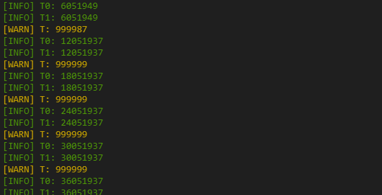
}After flashing your code, in your serial monitor, you should have an output similar to the one below:
The random module, like the time one, will be just a wrapper. On this case, a wrapper of ‘esp_random’.
random.h
The header file defines the ‘EspRandom’ class, which inherits from the ‘IRandom’ interface.
#ifndef _modules_rand_h_
#define _modules_rand_h_

#include <inttypes.h>
#include "../chip8/irandom.h"

class EspRandom: public IRandom
{
    public:
    bool init() override;
    void deinit() override;

    uint64_t next() override;
};

#endif
random.cpp
On the CPP file, ‘init’ and ‘deinit’ will be empty, and ‘next’ will return the value given by calling ‘esp_random’:
#include "random.h"
#include <Arduino.h>

bool EspRandom::init() { return true; }
void EspRandom::deinit() {}

uint64_t EspRandom::next() { return (uint64_t)esp_random(); }
main.cpp
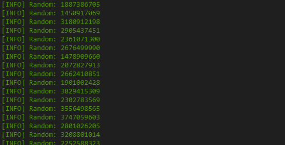
On the main file, include the modules and declare them. On setup, initialize the logger and on loop, generate a random number every second.
#include <Arduino.h>

#include "modules/logger.h"
#include "modules/time.h"
#include "modules/random.h"

EspLogger logger;
EspTime tm;
EspRandom rng;

void setup()
{
    logger.init();

    logger.info("Hello");
}

char buf[128];
void loop()
{
    uint64_t t0 = tm.getus();
    snprintf(buf, 128, "Random: %u", (uint32_t)rng.next());
    logger.info(buf);

    tm.waitms(1000);
}
After flashing your code, in your serial monitor, you should have an output similar to the one below:
The sound module, will use Arduino’s ‘ledc’ functions to make sound using a buzzer. As you probably noticed on the Hardware chapter of this article, I didn’t connect one. In the buzzer’s place, I made the built-in LED of the Esp32 blink when a sound was to be made. If you want to add sound to your console, simply connect a buzzer to pin 2 on your Esp.
sound.h
The header file defines the ‘EspSound’ class, which inherits from the ‘ISound’ interface. On this file, besides overriding the methods from the interface, we also create a constructor where we pass in all the variables needed to set up LEDC.
#ifndef _modules_sound_h_
#define _modules_sound_h_

#include <inttypes.h>
#include <Arduino.h>
#include "../chip8/isound.h"

class EspSound: public ISound
{
    uint8_t _channel;
    uint32_t _frequency;
    uint8_t _resolution;
    gpio_num_t _pin;

    public:
    EspSound(gpio_num_t pin, uint8_t c, uint32_t f, uint8_t r);

    bool init() override;
    void deinit() override;

    void play() override;
    void pause() override;
};

#endif
sound.cpp
On the CPP file, ‘init’ sets up LEDC, ‘play’ attaches the pin to the LEDC channel, ‘pause’ detaches it and ‘deinit’ calls ‘pause’:
#include "sound.h"
#include <Arduino.h>

EspSound::EspSound(gpio_num_t pin, uint8_t c, uint32_t f, uint8_t r)
{
    _pin = pin;
    _channel = c;
    _frequency = f;
    _resolution = r;
}

bool EspSound::init()
{
    // Setup buzzer pin
    pinMode(_pin, OUTPUT);
    digitalWrite(_pin, LOW);
    // Setup ledc channel
    ledcSetup(_channel, _frequency, _resolution);
    ledcWrite(_channel, 127);
    return true;
}
void EspSound::deinit() { pause(); }

void EspSound::play() { ledcAttachPin(_pin, _channel); }
void EspSound::pause() { ledcDetachPin(_pin); }
main.cpp
On the main file, include the modules and declare them. On setup, initialize the logger and sound and, on loop, turn the buzzer on for 500ms and off for 1500ms.
#include <Arduino.h>

#include "modules/logger.h"
#include "modules/time.h"
#include "modules/sound.h"

EspLogger logger;
EspTime tm;
EspSound sound(GPIO_NUM_2, 8, 440, 8);

void setup()
{
    logger.init();
    sound.init();

    logger.info("Hello");
}

void loop()
{
    logger.warn("Beep");

    sound.play();
    tm.waitms(500);

    sound.pause();
    tm.waitms(1500);
}
After flashing your code, you should see your built in LED flashing like this, and connecting a buzzer to pin 2 must also produce a sound:
The keyboard module suffered a lot of changes since our last article. In this project, the keyboard will be able to, not only tell you if a key is up or down, but also how much time it was held for and the exact frame where it was released. These new features will help us a lot while making the menu later.
keyboard.h
The header file defines the ‘EspKeyboard’ class, which inherits from the ‘IKeyboard’ interface. On this file, besides overriding the methods from the interface, we also create a constructor where we pass in the logger and 8 pins. The logger will be used on a new method named ‘serialDebug’, which will print the key states to Serial. Of the 8 pins we pass in the constructor, 4 will be output pins and the other 4 will be input. By setting one of the output pins as high, we can get which buttons are being clicked on that row.
Besides the methods and constructor, we will also need to declare a couple of variables. We will need two arrays of pins, 4 for output, 4 for input. A boolean to tell us if any of the pins is being pressed. A 2D 4 by 4 array that will store the button states. And, finally, a pointer to the logger, to be used in the debug method.
#ifndef _modules_keyboard_h_
#define _modules_keyboard_h_

#include <inttypes.h>
#include <Arduino.h>
#include "../chip8/ikeyboard.h"
#include "../chip8/ilogger.h"

class EspKeyboard: public IKeyboard
{
    gpio_num_t _inp[4];
    gpio_num_t _out[4];
    bool _any;
    int32_t _state[4][4];
    ILogger* _log;

    public:
    EspKeyboard(ILogger* logger, gpio_num_t po0, gpio_num_t po1, gpio_num_t po2, gpio_num_t po3,
            gpio_num_t pi0, gpio_num_t pi1, gpio_num_t pi2, gpio_num_t pi3);

    bool init() override;
    void deinit() override;

    void update(uint8_t* key_map) override;
    void update() override;

    int32_t getKey(uint8_t x, uint8_t y) override;
    bool anyPressed() override;

    void serialDebug();
};

#endif
keyboard.cpp
On the CPP file, we start by setting up the constructor. In it, we save the logger pointer and then store the pins on their respective arrays (in or out):
#include "keyboard.h"
#include <Arduino.h>

EspKeyboard::EspKeyboard(ILogger* logger, gpio_num_t po0, gpio_num_t po1, gpio_num_t po2, gpio_num_t po3,
                                          gpio_num_t pi0, gpio_num_t pi1, gpio_num_t pi2, gpio_num_t pi3)
{
    _log = logger;
    _out[0] = po0;
    _out[1] = po1;
    _out[2] = po2;
    _out[3] = po3;
    _inp[0] = pi0;
    _inp[1] = pi1;
    _inp[2] = pi2;
    _inp[3] = pi3;
}
The ‘init’ method will initialize all output pins, set them to LOW, and also set all input pins as input. The ‘deinit’ method will remain empty:
bool EspKeyboard::init()
{
    pinMode(_out[0], OUTPUT);
    pinMode(_out[1], OUTPUT);
    pinMode(_out[2], OUTPUT);
    pinMode(_out[3], OUTPUT);

    digitalWrite(_out[0], LOW);
    digitalWrite(_out[1], LOW);
    digitalWrite(_out[2], LOW);
    digitalWrite(_out[3], LOW);

    pinMode(_inp[0], INPUT);
    pinMode(_inp[1], INPUT);
    pinMode(_inp[2], INPUT);
    pinMode(_inp[3], INPUT);

    return true;
}

void EspKeyboard::deinit() { }
On ‘update’, the one with no arguments, we start by resetting the ‘any’ flag, after that we loop for every row and read every column, if a button is pressed, we increase the state and set ‘any’ as true, if the button isn’t pressed, we check if the state is not zero, and if it isn’t, we set state to 0 if it was released last frame, or to -1 if it was released this frame.
After updating every button’s state, we check if the buttons 9 and D were pressed for more than 30 ticks (half a second), if that is true, we restart the Esp. This will be useful to exit a game or to avoid any bugs that the display might give us later:
void EspKeyboard::update()
{
    _any = false; // reset any flag
    for (uint8_t x = 0; x < 4; x++) // for each row
    {
        digitalWrite(_out[x], HIGH);
        for (uint8_t y = 0; y < 4; y++) // for each column
        {
            if (digitalRead(_inp[y])) // if pressed
            {
                _state[y][x]++; // increase hold time
                _any = true; // set any to true
            }
            else if (_state[y][x]) // not pressed and state not 0
            {
                if (_state[y][x] < 0) // if released on last frame, set to 0
                    _state[y][x] = 0;
                else _state[y][x] = -1; // if released on this frame, set to -1
            }
        }
        digitalWrite(_out[x], LOW);
    }

    // Force reset
    const uint16_t holdTime = 30; // Trigger before other 1sec actions
    if (_state[2][2] > holdTime && _state[3][3] > holdTime)
    {
        _log->warn("Reset combo Held for half a second, rebooting...");
        ESP.restart();
    }
}
The other ‘update’, the one that accepts a key map, will call the ‘update’ method with no arguments, to get the latest keyboard state. After that, we will save the state to the key map in a way that the Chip8 emulator understands (true or falses):
void EspKeyboard::update(uint8_t* key_map)
{
    // update keys
    update();

    // 1 2 3 C
    key_map[0x1] = _state[0][0] > 0;
    key_map[0x2] = _state[0][1] > 0;
    key_map[0x3] = _state[0][2] > 0;
    key_map[0xC] = _state[0][3] > 0;

    // 4 5 6 D
    key_map[0x4] = _state[1][0] > 0;
    key_map[0x5] = _state[1][1] > 0;
    key_map[0x6] = _state[1][2] > 0;
    key_map[0xD] = _state[1][3] > 0;

    // 7 8 9 E
    key_map[0x7] = _state[2][0] > 0;
    key_map[0x8] = _state[2][1] > 0;
    key_map[0x9] = _state[2][2] > 0;
    key_map[0xE] = _state[2][3] > 0;

    // A 0 B F
    key_map[0xA] = _state[3][0] > 0;
    key_map[0x0] = _state[3][1] > 0;
    key_map[0xB] = _state[3][2] > 0;
    key_map[0xF] = _state[3][3] > 0;
}
The ‘getKey’ method will return the state of a button from the 2D array and, the ‘anyPressed’ method will return true if any of the keys is being held this frame:
int32_t EspKeyboard::getKey(uint8_t x, uint8_t y)
{
    if (x > 3)
        x = 3;
    if (y > 3)
        y = 3;
    return _state[y][x];
}

bool EspKeyboard::anyPressed() { return _any; }
Finally, the ‘serialDebug’ method will loop through every key and log it’s state to Serial. Note that i clamp the held time to 99 to better read the output in the Serial Monitor, but the real hold time can go to 4 billion (uint32_t max value):
void EspKeyboard::serialDebug()
{
    const static uint8_t bufsize = 128;
    char buf[bufsize];
    uint32_t p = snprintf(buf, bufsize, "Keyboard state:\n");
    for (uint8_t y = 0; y < 4; y++)
    {
        p += snprintf(buf + p, bufsize - p, "        ");
        for (uint8_t x = 0; x < 4; x++)
            p += snprintf(buf + p, bufsize - p, "%02d ", (_state[y][x] > 99) ? 99 : _state[y][x]);
            p += snprintf(buf + p, bufsize - p, "\n");
    }
    _log->log(buf);
}
main.cpp
On the main file, include the modules and declare them. On setup, initialize the logger and keyboard and, on loop, update the keyboard, log it and sleep for enough time to make it run at 60Hz:
#include <Arduino.h>
#include "modules/logger.h"
#include "modules/time.h"
#include "modules/keyboard.h"
EspLogger logger;
EspTime tm;
EspKeyboard keyboard(&logger, GPIO_NUM_26, GPIO_NUM_25, GPIO_NUM_33, GPIO_NUM_32,
GPIO_NUM_35, GPIO_NUM_34, GPIO_NUM_39, GPIO_NUM_36 );
void setup()
{
logger.init();
keyboard.init();
logger.info("Hello");
}
char buf[128];
void loop()
{
uint64_t t0 = tm.getus();
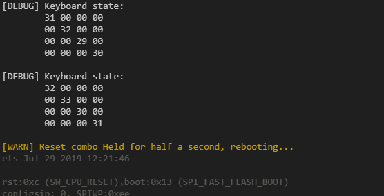
keyboard.update();
keyboard.serialDebug();
int64_t sleepTime = (1000000 / 60) - (int64_t)(tm.getus() - t0);
if (sleepTime > 0)
tm.waitus(sleepTime);
}After flashing your code, in your serial monitor, you should have an output similar to the one below. Also, by holding 1+5+9+D you Esp should reboot:
The display module will provide all methods defined in ‘IDisplay’ and one to get a pointer to the display driver, this new method will let us have better control of what we draw to the screen later while coding the menu.
display.h
The header file defines the ‘EspDisplay’ class, which inherits from the ‘IDisplay’ interface. On this file, besides overriding the methods from the interface, we will also create a method to return the pointer to the display driver, a frame buffer, the driver itself, 3 pins (Chip Select, Data Command and Reset) and some constants to help us in the CPP file:
#ifndef _modules_display_h_
#define _modules_display_h_

#include <inttypes.h>
#include <Arduino.h>
#include "../chip8/idisplay.h"
#include <Adafruit_GFX.h>
#include <Adafruit_ST7735.h>

class EspDisplay: public IDisplay
{
    const static uint16_t _size_x = 160;
    const static uint16_t _size_y = 128;
    const static uint16_t _col_0 = 0b0001100001100011; // gray?
    const static uint16_t _col_1 = 0b0000011111100000; // green
    const static uint16_t _zoom = 2;
    gpio_num_t _cs, _dc, _rst;
    Adafruit_ST7735 _disp = Adafruit_ST7735(GPIO_NUM_NC, GPIO_NUM_NC, GPIO_NUM_NC);
    uint16_t _framebuf[_size_x * _size_y];

    public:
    EspDisplay(gpio_num_t cs, gpio_num_t dc, gpio_num_t rst);

    bool init() override;
    void deinit() override;

    void draw(uint8_t* framebuf, uint8_t w, uint8_t h) override;
    void update(uint8_t w, uint8_t h) override;

    Adafruit_ST7735* getDisplay();
};

#endif
display.cpp
On the CPP file, we start by setting up the constructor. In it, we save the pins and create the driver:
#include "display.h"
#include <Arduino.h>

EspDisplay::EspDisplay(gpio_num_t cs, gpio_num_t dc, gpio_num_t rst)
{
    _cs = cs;
    _dc = dc;
    _rst = rst;
    _disp = Adafruit_ST7735(cs, dc, rst);
}
On ‘init’, we set the display’s pins as output, initialize it, set rotation 90º, fill the screen with black, disable text wrapping and set the cursor to the top left of the display. The ‘deinit’ method will remain empty.
// Intializes the display
bool EspDisplay::init()
{
    pinMode(_cs, OUTPUT);
    pinMode(_dc, OUTPUT);
    pinMode(_rst, OUTPUT);

    // Init display
    _disp.initR(INITR_GREENTAB);
    _disp.setRotation(1); // rotate 90º
    _disp.invertDisplay(false);
    _disp.fillScreen(ST7735_BLACK);
    _disp.setTextWrap(false);
    _disp.setCursor(1,1);
    return true;
}
// No code needs to be called here
void EspDisplay::deinit() { }On ‘draw’, we read from the frame buffer that comes from the Chip8 display, scale it according to the ‘_zoom’ variable and write it to our display’s frame buffer:
void EspDisplay::draw(uint8_t* framebuf, uint8_t w, uint8_t h)
{
    for (uint8_t y = 0; y < h; y++)
        for (uint8_t x = 0; x < w; x++)
        {
            uint16_t color = framebuf[y * w + x] ? _col_1 : _col_0; // Calculate color from pixel
            uint16_t y0 = y * _zoom * (w * _zoom); // Calculate y value
            uint16_t x0 = x * _zoom; // Calculate x value
            // Paint 2 by 2 "pixel"
            _framebuf[y0 + x0] = color;
            _framebuf[y0 + x0 + 1] = color;
            _framebuf[y0 + (w * _zoom) + x0] = color;
            _framebuf[y0 + (w * _zoom) + x0 + 1] = color;
        }
}On ‘update’, we calculate the position to draw our image at the center of the display and send our frame buffer to the display using the ‘drawRGBBitmap’ method. Finally, the ‘getDisplay’ method, returns a pointer to the display driver.
void EspDisplay::update(uint8_t w, uint8_t h)
{
    const uint16_t x0 = (_size_x - (w * _zoom)) / 2;
    const uint16_t y0 = (_size_y - (h * _zoom)) / 2;
    _disp.drawRGBBitmap(x0, y0, _framebuf, w * _zoom, h * _zoom);
}

Adafruit_ST7735* EspDisplay::getDisplay() { return &_disp; }
main.cpp
On the main file, include the modules and declare them. On setup, initialize the logger and display. On loop, get current time, draw to the buffer, update the display and sleep enough to run the loop at 60 Hz:
#include <Arduino.h>

#include "modules/logger.h"
#include "modules/time.h"
#include "modules/display.h"
#include "pins.h"

EspLogger logger;
EspTime tm;
EspDisplay display(DISP_CS, DISP_DC, DISP_RST);

const uint16_t bufSize = 64 * 32;
uint8_t buf[bufSize] = {0};

void setup()
{
    logger.init();
    tm.init();
    display.init();
}

uint16_t i = 0;
void loop()
{
    uint64_t t0 = tm.getus();

    uint16_t li = i;
    i = (i + 1 >= bufSize) ? 0 : i + 1;

    buf[li] = 0;
    buf[i] = 1;

    display.draw(buf, 64, 32);
    display.update(64, 32);

    int64_t sleepTime = (1000000 / 120) - ((int64_t)tm.getus() - t0);
    if (sleepTime > 0)
        tm.waitus(sleepTime);
}
After flashing your code, on your display, you should see something like this:
After adding and testing every single one of your modules, check if you aren’t missing any. Below you can find the file structure that your project must have before proceeding:
📂 esp32-c8console
├── 📄platformio.ini
└── 📂 src
    ├── 📂 chip8
    │   ├── 📄idisplay.h
    │   ├── 📄ikeyboard.h
    │   ├── 📄ilogger.h
    │   ├── 📄irandom.h
    │   ├── 📄isound.h
    │   └── 📄itime.h
    ├── 📂 modules
    │   ├── 📄display.cpp
    │   ├── 📄display.h
    │   ├── 📄keyboard.cpp
    │   ├── 📄keyboard.h
    │   ├── 📄logger.cpp
    │   ├── 📄logger.h
    │   ├── 📄random.cpp
    │   ├── 📄random.h
    │   ├── 📄sound.cpp
    │   ├── 📄sound.h
    │   ├── 📄time.cpp
    │   └── 📄time.h
    ├── 📄main.cpp
└── 📄pins.hNow we will start to code the emulator. The emulator consists of one header and one CPP file (plus the interfaces we created earlier). Both of these files will be placed inside the ‘chip8’ folder.
Once again, if you want to check our other articles about the Chip8, click here to go to the links.
chip8.h
On the header file of the emulator, we will start by including all the interfaces we created earlier:
#ifndef _chip8_chip8_h_
#define _chip8_chip8_h_

#include "idisplay.h"
#include "ikeyboard.h"
#include "ilogger.h"
#include "irandom.h"
#include "isound.h"
#include "itime.h"

// code below goes here...

#endif
Next we will define some constants. Most of these will help us declare buffers later, for example, ram and frame buffers.
#define C8_KEYCOUNT 16      // ammount of keys our keyboard has
#define C8_TOTALRAM 4096    // Chip8's ram size
#define C8_STACKSIZE 16     // Chip8's stack size
#define C8_FONTSETSIZE 80   // Chip8's fontset size
#define C8_TIMERMAX 255     // Chip8's timers max value

#define C8_RAMSTART 0x000   // RAM's start address
#define C8_RAMEND 0x1FF     // RAM's end address
#define C8_PROGSTART 0x200  // Program memory start address
#define C8_PROGEND 0xFFF    // Progmem end adr
#define C8_PROGSIZE (C8_PROGEND - C8_PROGSTART) // Progmem size

#define C8_REGISTERCOUNT 16 // Ammount of registers the Chip8's CPU has

#define C8_SCREEN_W 64      // Width of the display
#define C8_SCREEN_H 32      // Height of the display

#define C8_SCREENTARGET 16666 // Sleep time in us to achieve 60Hz
Next, we create the font set. This will then be loaded to ram so that programs can write text and numbers to the screen easily.
const static uint8_t C8_FONTSET[] = {
    0xF0, 0x90, 0x90, 0x90, 0xF0, // 0
    0x20, 0x60, 0x20, 0x20, 0x70, // 1
    0xF0, 0x10, 0xF0, 0x80, 0xF0, // 2
    0xF0, 0x10, 0xF0, 0x10, 0xF0, // 3
    0x90, 0x90, 0xF0, 0x10, 0x10, // 4
    0xF0, 0x80, 0xF0, 0x10, 0xF0, // 5
    0xF0, 0x80, 0xF0, 0x90, 0xF0, // 6
    0xF0, 0x10, 0x20, 0x40, 0x40, // 7
    0xF0, 0x90, 0xF0, 0x90, 0xF0, // 8
    0xF0, 0x90, 0xF0, 0x10, 0xF0, // 9
    0xF0, 0x90, 0xF0, 0x90, 0x90, // A
    0xE0, 0x90, 0xE0, 0x90, 0xE0, // B
    0xF0, 0x80, 0x80, 0x80, 0xF0, // C
    0xE0, 0x90, 0x90, 0x90, 0xE0, // D
    0xF0, 0x80, 0xF0, 0x80, 0xF0, // E
    0xF0, 0x80, 0xF0, 0x80, 0x80  // F
};
Then we move onto our Chip8 class, in it, declare pointers to our modules:
class Chip8
{
    // Modules
    IDisplay* _display;
    IKeyboard* _keyboard;
    ILogger* _logger;
    IRandom* _random;
    ISound* _sound;
    ITime* _time;

    // code below goes here...
};
After that, we create a variable to keep track of our clock speed and also the buffers. A draw buffer, the keyboard state, ram, and stack:
// Target Hz
uint16_t _clock;

// Buffers
uint8_t _drawbuf[C8_SCREEN_H][C8_SCREEN_W];
uint8_t _keys[C8_KEYCOUNT];
uint8_t _ram[C8_TOTALRAM];
uint16_t _stack[C8_STACKSIZE];
Then we move to the CPU registers, create an array for the 16 general purpose registers, the 16bit I register, program counter, stack pointer and two helper variables to get the instruction and op code:
// Registers
uint8_t _reg[C8_REGISTERCOUNT];
uint16_t _ireg;
uint16_t _pcreg;
uint16_t _spreg;
uint16_t _opcode;
uint16_t _instr;
Now the only variables remaining are the timers. We will have that the games will be able to use, named delay and the other named sound that, as long as it is non-zero, the buzzer will make sound. Below the two Chip8 timers, we will also create a 64bit unsigned int to keep track of the last time that screen was updated at, this will let us update the screen and timers at 60Hz:
// Timers
uint8_t _timer_delay;
uint8_t _timer_sound;
uint64_t _time_lastscreenupdate;
The next three methods handle the CPU, ‘fetch’ gets the next OP code, ‘decode’ extracts the instruction from the OP code and ‘execute’ executes the instruction:
// CPU
void fetch();
void decode();
void execute();
And finally, to end the private methods of the Chip8 class, we will define the instructions. You can read about them in this document.
// Instructions implementation
void decode_0_instruction();                        // 0ZZZ
void clear_screen();                                // 0ZE0
void return_from_subroutine();                      // 0ZEE
void jump_to();                                     // 1NNN
void call_subroutine();                             // 2NNN
void skip_next_instruction_eq();                    // 3XNN
void skip_next_instruction_ne();                    // 4XNN
void skip_next_instruction_vx_vy();                 // 5XYZ
void register_set();                                // 6XNN
void add_reg_imm();                                 // 7XNN
void decode_8_instruction();                        // 8XYZ
void move_vy_to_vx();                               // 8XY0
void or_vx_vy();                                    // 8XY1
void and_vx_vy();                                   // 8XY2
void xor_vx_vy();                                   // 8XY3
void add_vx_vy();                                   // 8XY4
void sub_vx_vy();                                   // 8XY5
void shift_right_reg();                             // 8XY6
void subn_vx_vy();                                  // 8XY7
void shift_left_reg();                              // 8XYE
void skip_next_instruction_vx_vy_ne();              // 9XYZ
void set_index_register();                          // ANNN
void jump_with_v0();                                // BNNN
void generate_random_number();                      // CXKK
void draw_sprite();                                 // DXYN
void decode_E_instruction();                        // EZZZ
void skip_next_inst_if_key_pressed();               // EX9E
void skip_next_inst_if_not_pressed();               // EXA1
void decode_F_instruction();                        // FZZZ
void load_reg_with_delay_timer();                   // FX07
void wait_key_press();                              // FX0A
void load_delay_timer_with_reg();                   // FX15
void load_sound_timer_with_reg();                   // FX18
void add_ireg_with_reg();                           // FX1E
void load_font_from_vx();                           // FX29
void store_binary_code_decimal_representation();    // FX33
void load_memory_from_regs();                       // FX55
void load_regs_from_memory();                       // FX65
As for public methods, we will have three and a constructor. The constructor takes in the modules, ‘init’ load a ROM and sets the clock speed, ‘deinit’ deinitializes the modules and, lastly, ‘tick’ runs one step of the emulation:
public:
Chip8(IDisplay* display, IKeyboard* keyboard, ILogger* logger, IRandom* random, ISound* sound, ITime* time);

bool init(const uint8_t* rom, uint16_t romSize, uint16_t clock = 700);
void deinit();

int64_t tick();
chip8.cpp
On the CPP file, we start by setting up the constructor. In it, we save the modules and clock:
#include "chip8.h"

Chip8::Chip8(IDisplay* display, IKeyboard* keyboard, ILogger* logger, IRandom* random, ISound* sound, ITime* time)
{
    _display = display;
    _keyboard = keyboard;
    _logger = logger;
    _random = random;
    _sound = sound;
    _time = time;
    _clock = 700;
}
Next, we create the ‘init’ function, in it, we initialize the logger, check the ROM size, initialize the other modules, and then clear the frame buffer, ram, registers and load the font and ROM:
bool Chip8::init(const uint8_t* rom, uint16_t romSize, uint16_t clock)
{
    // Init logger
    if (!_logger->init())
        return false;

    // Check rom size
    if (!rom || !romSize || romSize > (C8_PROGEND - C8_PROGSTART))
    {
        _logger->error("C8: Invalid ROM");
        return false;
    }

    // Init modules
    if (!_display->init())
    {
        _logger->error("C8: Can't init display");
        return false;
    }
    if (!_keyboard->init())
    {
        _logger->error("C8: Can't init display");
        return false;
    }
    if (!_random->init())
    {
        _logger->error("C8: Can't init random");
        return false;
    }
    if (!_sound->init())
    {
        _logger->error("C8: Can't init sound");
        return false;
    }
    if (!_time->init())
    {
        _logger->error("C8: Can't init time");
        return false;
    }

    // Initialize registers and buffers
    for (uint16_t y = 0; y < C8_SCREEN_H; y++)
        for (uint16_t x = 0; x < C8_SCREEN_W; x++)
            _drawbuf[y][x] = 0;

    for (uint16_t i = 0; i < C8_STACKSIZE; i++)
        _stack[i] = 0;

    for (uint16_t i = 0; i < C8_TOTALRAM; i++)
        _ram[i] = 0;

    for (uint16_t i = 0; i < C8_REGISTERCOUNT; i++)
        _reg[i] = 0;

    _timer_delay = 0;
    _timer_sound = 0;

    _pcreg = C8_PROGSTART;
    _clock = clock;
    _opcode = 0;
    _instr = 0;
    _spreg = 0;
    _ireg = 0;

    // Load font
    for (uint16_t i = 0; i < C8_FONTSETSIZE; i++)
        _ram[i] = C8_FONTSET[i];

    // Load ROM
    for (uint16_t i = 0; i < romSize; i++)
        _ram[C8_PROGSTART + i] = rom[i];

    _logger->log("C8: Emulator ready");
    return true;
}
The ‘deinit’ method simply calls ‘deinit’ for every module:
void Chip8::deinit()
{
    _display->deinit();
    _keyboard->deinit();
    _random->deinit();
    _sound->deinit();
    _time->deinit();
}
The ‘tick’ method gets the current time and executes a CPU cycle. If enough time as passed (about 16ms), we also update the keyboard, screen, timers, and sound:
int64_t Chip8::tick()
{
    uint64_t t0 = _time->getus(); // Get current time

    // CPU
    fetch();
    decode();
    execute();

    // Run at 60Hz
    if (t0 > (_time_lastscreenupdate + C8_SCREENTARGET))
    {
        _time_lastscreenupdate = t0; // save time
        // update keyboard
        _keyboard->update(_keys);
        // draw frame
        _display->draw((uint8_t*)_drawbuf, C8_SCREEN_W, C8_SCREEN_H);
        _display->update(C8_SCREEN_W, C8_SCREEN_H);

        // Decrease delay timer
        if (_timer_delay > 0)
            _timer_delay--;
        // Decrease sound time
        if (_timer_sound > 0)
        {
            _timer_sound--;
            _sound->play(); // make sound
        }
        else _sound->pause(); // stop sound
    }

    // Calculate and return the sleep time
    return (int64_t)(1000000u / _clock) - (int64_t)(_time->getus() - t0);
}
The ‘fetch’ method loads the next OP code and ‘decode’ extracts the instruction from it:
void Chip8::fetch()
{
    _opcode = ((uint16_t)_ram[_pcreg] << 8) | _ram[_pcreg + 1];
    _pcreg += 2;
}

void Chip8::decode()
{
    _instr = _opcode >> 12;
}
The ‘execute’ method calls the correct instruction of the CPU:
void Chip8::execute()
{
    switch (_instr)
    {
        case 0x0: decode_0_instruction();           break;
        case 0x1: jump_to();                        break;
        case 0x2: call_subroutine();                break;
        case 0x3: skip_next_instruction_eq();       break;
        case 0x4: skip_next_instruction_ne();       break;
        case 0x5: skip_next_instruction_vx_vy();    break;
        case 0x6: register_set();                   break;
        case 0x7: add_reg_imm();                    break;
        case 0x8: decode_8_instruction();           break;
        case 0x9: skip_next_instruction_vx_vy_ne(); break;
        case 0xA: set_index_register();             break;
        case 0xB: jump_with_v0();                   break;
        case 0xC: generate_random_number();         break;
        case 0xD: draw_sprite();                    break;
        case 0xE: decode_E_instruction();           break;
        case 0xF: decode_F_instruction();           break;
        default: _logger->error("C8: IMPOSSIBLE INSTRUCTION");
    }
}
chip8.cpp (CPU instructions)
Below you can see all standard Chip8 instructions, if you want to implement them by yourself, you can go to this webpage to check out the Technical Reference and get a rough idea of what you need to implement.
/*****************************
 * 0ZZZ
 *****************************/
void Chip8::decode_0_instruction()
{
    switch (_opcode & 0xFF)
    {
        case 0xE0: clear_screen(); break;
        case 0xEE: return_from_subroutine(); break;
        default: _logger->error("C8: IMPOSSIBLE 0 INSTRUCTION");
    }
}
/*****************************
* 0ZE0
*****************************/
void Chip8::clear_screen()
{
for (int i = 0; i < C8_SCREEN_H; i++)
for (int j = 0; j < C8_SCREEN_W; j++)
_drawbuf[i][j] = 0;
}/*****************************
* 0ZEE
*****************************/
void Chip8::return_from_subroutine()
{
_spreg--;
_pcreg = _stack[_spreg];
}/*****************************
* 1NNN
*****************************/
void Chip8::jump_to()
{
_pcreg = _opcode & 0x0FFF;
}/*****************************
* 2NNN
*****************************/
void Chip8::call_subroutine()
{
uint16_t nnn = _opcode & 0x0FFF;
_stack[_spreg] = _pcreg;
_spreg++;
_pcreg = nnn;
}/*****************************
* 3XNN
*****************************/
void Chip8::skip_next_instruction_eq()
{
uint8_t value = _opcode & 0xFF;
uint8_t reg = (_opcode >> 8) & 0x0F;
if (_reg[reg] == value)
_pcreg += 2;
}/*****************************
* 4XNN
*****************************/
void Chip8::skip_next_instruction_ne()
{
uint8_t value = _opcode & 0xFF;
uint8_t reg = (_opcode >> 8) & 0x0F;
if (_reg[reg] != value)
_pcreg += 2;
}/*****************************
* 5XYZ
*****************************/
void Chip8::skip_next_instruction_vx_vy()
{
uint8_t reg_x = (_opcode >> 8) & 0x0F;
uint8_t reg_y = (_opcode >> 4) & 0x0F;
if (_reg[reg_x] == _reg[reg_y])
_pcreg += 2;
}/*****************************
* 6XNN
*****************************/
void Chip8::register_set()
{
uint8_t value = _opcode & 0xFF;
uint8_t reg = (_opcode >> 8) & 0x0F;
_reg[reg] = value;
}/*****************************
* 7XNN
*****************************/
void Chip8::add_reg_imm()
{
uint8_t value = _opcode & 0xFF;
uint8_t reg = (_opcode >> 8) & 0x0F;
_reg[reg] += value;
}/*****************************
* 8XYZ
*****************************/
void Chip8::decode_8_instruction()
{
switch (_opcode & 0xF)
{
case 0x0: move_vy_to_vx(); break;
case 0x1: or_vx_vy(); break;
case 0x2: and_vx_vy(); break;
case 0x3: xor_vx_vy(); break;
case 0x4: add_vx_vy(); break;
case 0x5: sub_vx_vy(); break;
case 0x6: shift_right_reg(); break;
case 0x7: subn_vx_vy(); break;
case 0xE: shift_left_reg(); break;
default: _logger->error("C8: IMPOSSIBLE 8 INSTRUCTION");
}
}/*****************************
* 8XY0
*****************************/
void Chip8::move_vy_to_vx()
{
uint8_t reg_x = (_opcode >> 8) & 0x0F;
uint8_t reg_y = (_opcode >> 4) & 0x0F;
_reg[reg_x] = _reg[reg_y];
}/*****************************
* 8XY1
*****************************/
void Chip8::or_vx_vy()
{
uint8_t reg_x = (_opcode >> 8) & 0x0F;
uint8_t reg_y = (_opcode >> 4) & 0x0F;
_reg[reg_x] |= _reg[reg_y];
}/*****************************
* 8XY2
*****************************/
void Chip8::and_vx_vy()
{
uint8_t reg_x = (_opcode >> 8) & 0x0F;
uint8_t reg_y = (_opcode >> 4) & 0x0F;
_reg[reg_x] &= _reg[reg_y];
}/*****************************
* 8XY3
*****************************/
void Chip8::xor_vx_vy()
{
uint8_t reg_x = (_opcode >> 8) & 0x0F;
uint8_t reg_y = (_opcode >> 4) & 0x0F;
_reg[reg_x] ^= _reg[reg_y];
}/*****************************
* 8XY4
*****************************/
void Chip8::add_vx_vy()
{
uint8_t reg_x = (_opcode >> 8) & 0x0F;
uint8_t reg_y = (_opcode >> 4) & 0x0F;
uint16_t add = _reg[reg_x] + _reg[reg_y];
if (add > 0xFF)
_reg[0xF] = 1;
else
_reg[0xF] = 0;
_reg[reg_x] = add & 0xFF;
}/*****************************
* 8XY5
*****************************/
void Chip8::sub_vx_vy()
{
uint8_t reg_x = (_opcode >> 8) & 0x0F;
uint8_t reg_y = (_opcode >> 4) & 0x0F;
if (_reg[reg_x] > _reg[reg_y])
_reg[0xF] = 1;
else
_reg[0xF] = 0;
_reg[reg_x] -= _reg[reg_y];
}/*****************************
* 8XY6
*****************************/
void Chip8::shift_right_reg()
{
uint8_t reg = (_opcode >> 8) & 0x0F;
if (_reg[reg] % 2 == 1)
_reg[0xF] = 1;
else
_reg[0xF] = 0;
_reg[reg] >>= 1;
}/*****************************
* 8XY7
*****************************/
void Chip8::subn_vx_vy()
{
uint8_t reg_x = (_opcode >> 8) & 0x0F;
uint8_t reg_y = (_opcode >> 4) & 0x0F;
if (_reg[reg_y] > _reg[reg_x])
_reg[0xF] = 1;
else
_reg[0xF] = 0;
_reg[reg_x] = _reg[reg_y] - _reg[reg_x];
}/*****************************
* 8XYE
*****************************/
void Chip8::shift_left_reg()
{
uint8_t reg = (_opcode >> 8) & 0x0F;
if (_reg[reg] & 0x80 == 1)
_reg[0xF] = 1;
else
_reg[0xF] = 0;
_reg[reg] <<= 1;
}/*****************************
* 9XYZ
*****************************/
void Chip8::skip_next_instruction_vx_vy_ne()
{
uint8_t reg_x = (_opcode >> 8) & 0x0F;
uint8_t reg_y = (_opcode >> 4) & 0x0F;
if (_reg[reg_x] != _reg[reg_y])
_pcreg += 2;
}/*****************************
* ANNN
*****************************/
void Chip8::set_index_register()
{
_ireg = _opcode & 0x0FFF;
}/*****************************
* BNNN
*****************************/
void Chip8::jump_with_v0()
{
uint16_t nnn = _opcode & 0x0FFF;
_pcreg = nnn + _reg[0];
}/*****************************
* CXKK
*****************************/
void Chip8::generate_random_number()
{
uint8_t reg = (_opcode >> 8) & 0x0F;
uint8_t kk = _opcode & 0xFF;
uint8_t randNum = _random->next() % 256;
_reg[reg] = randNum & kk;
}/*****************************
* DXYN
*****************************/
void Chip8::draw_sprite()
{
uint8_t v_reg_x = (_opcode & 0x0F00) >> 8;
uint8_t v_reg_y = (_opcode & 0x00F0) >> 4;
uint8_t sprite_height = _opcode & 0x000F;
uint8_t x_location = _reg[v_reg_x];
uint8_t y_location = _reg[v_reg_y];
_reg[0xF] = 0; // Reset colision register
for (int y_coordinate = 0; y_coordinate < sprite_height; y_coordinate++)
{
uint8_t pixel = _ram[_ireg + y_coordinate]; // Get pixel
for (int x_coordinate = 0; x_coordinate < 8; x_coordinate++)
{
if ((pixel & (0x80 >> x_coordinate)) != 0)
{
uint8_t xx = (x_location + x_coordinate) % C8_SCREEN_W; // Wrap around
uint8_t yy = (y_location + y_coordinate) % C8_SCREEN_H; // Wrap around
if (_drawbuf[yy][xx] == 1) // Set collision register
_reg[0xF] = 1;
_drawbuf[yy][xx] ^= 0x1; // Flip pixel
}
}
}
}/*****************************
* EZZZ
*****************************/
void Chip8::decode_E_instruction()
{
switch (_opcode & 0xFF)
{
case 0x009E: skip_next_inst_if_key_pressed(); break;
case 0x00A1: skip_next_inst_if_not_pressed(); break;
default: _logger->error("C8: IMPOSSIBLE E INSTRUCTION");
}
}/*****************************
* EX9E
*****************************/
void Chip8::skip_next_inst_if_key_pressed()
{
uint8_t reg = (_opcode >> 8) & 0x0F;
uint8_t val = _reg[reg];
if (_keys[val] != 0)
_pcreg += 2;
}/*****************************
* EXA1
*****************************/
void Chip8::skip_next_inst_if_not_pressed()
{
uint8_t reg = (_opcode >> 8) & 0x0F;
uint8_t val = _reg[reg];
if (_keys[val] == 0)
_pcreg += 2;
}/*****************************
* FZZZ
*****************************/
void Chip8::decode_F_instruction()
{
switch (_opcode & 0xFF)
{
case 0x0007: load_reg_with_delay_timer(); break;
case 0x000A: wait_key_press(); break;
case 0x0015: load_delay_timer_with_reg(); break;
case 0x0018: load_sound_timer_with_reg(); break;
case 0x001E: add_ireg_with_reg(); break;
case 0x0029: load_font_from_vx(); break;
case 0x0033: store_binary_code_decimal_representation(); break;
case 0x0055: load_memory_from_regs(); break;
case 0x0065: load_regs_from_memory(); break;
default: _logger->error("C8: IMPOSSIBLE F INSTRUCTION");
}
}/*****************************
* FX07
*****************************/
void Chip8::load_reg_with_delay_timer()
{
uint8_t reg = (_opcode >> 8) & 0x0F;
_reg[reg] = _timer_delay;
}/*****************************
* FX0A
*****************************/
void Chip8::wait_key_press()
{
uint8_t reg = (_opcode >> 8) & 0x0F;
bool key_pressed = false;
for (int i = 0; i < C8_KEYCOUNT; i++)
{
if (_keys[i] != 0)
{
_reg[reg] = i;
key_pressed = true;
}
}
if (!key_pressed)
_pcreg -= 2;
}/*****************************
* FX15
*****************************/
void Chip8::load_delay_timer_with_reg()
{
uint8_t reg = (_opcode >> 8) & 0x0F;
_timer_delay = _reg[reg];
}/*****************************
* FX18
*****************************/
void Chip8::load_sound_timer_with_reg()
{
uint8_t reg = (_opcode >> 8) & 0x0F;
_timer_sound = _reg[reg];
}/*****************************
* FX1E
*****************************/
void Chip8::add_ireg_with_reg()
{
uint8_t reg = (_opcode >> 8) & 0x0F;
_ireg += _reg[reg];
}/*****************************
* FX29
*****************************/
void Chip8::load_font_from_vx()
{
uint8_t reg = (_opcode >> 8) & 0x0F;
_ireg = _reg[reg] * 0x5;
}/*****************************
* FX33
*****************************/
void Chip8::store_binary_code_decimal_representation()
{
uint8_t reg = (_opcode >> 8) & 0x0F;
_ram[_ireg] = _reg[reg] / 100;
_ram[_ireg + 1] = (_reg[reg] / 10) % 10;
_ram[_ireg + 2] = _reg[reg] % 10;
}/*****************************
* FX55
*****************************/
void Chip8::load_memory_from_regs()
{
uint8_t reg = (_opcode >> 8) & 0x0F;
for (int i = 0; i <= reg; i++)
_ram[_ireg + i] = _reg[i];
_ireg += (reg + 1);
}/*****************************
* FX65
*****************************/
void Chip8::load_regs_from_memory()
{
uint8_t reg = (_opcode >> 8) & 0x0F;
for (int i = 0; i <= reg; i++)
_reg[i] = _ram[_ireg + i];
_ireg += (reg + 1);
}
main.cpp
Before we create the main file, let’s make a ‘roms.h’ file that will contain our test ROM, the ‘Keypad Test’:
#ifndef _roms_h_
#define _roms_h_

#include <Arduino.h>

// Keypad Test, by hap, 15-02-06
// press a chip8 key and the pressed char will light up
static const uint8_t rom_KeypadTest[] = {
    0x12, 0x4e, 0x08, 0x19, 0x01, 0x01, 0x08, 0x01, 0x0f, 0x01, 0x01, 0x09, 0x08, 0x09, 0x0f, 0x09,
    0x01, 0x11, 0x08, 0x11, 0x0f, 0x11, 0x01, 0x19, 0x0f, 0x19, 0x16, 0x01, 0x16, 0x09, 0x16, 0x11,
    0x16, 0x19, 0xfc, 0xfc, 0xfc, 0xfc, 0xfc, 0xfc, 0xfc, 0x00, 0xa2, 0x02, 0x82, 0x0e, 0xf2, 0x1e,
    0x82, 0x06, 0xf1, 0x65, 0x00, 0xee, 0xa2, 0x02, 0x82, 0x0e, 0xf2, 0x1e, 0x82, 0x06, 0xf1, 0x55,
    0x00, 0xee, 0x6f, 0x10, 0xff, 0x15, 0xff, 0x07, 0x3f, 0x00, 0x12, 0x46, 0x00, 0xee, 0x00, 0xe0,
    0x62, 0x00, 0x22, 0x2a, 0xf2, 0x29, 0xd0, 0x15, 0x70, 0xff, 0x71, 0xff, 0x22, 0x36, 0x72, 0x01,
    0x32, 0x10, 0x12, 0x52, 0xf2, 0x0a, 0x22, 0x2a, 0xa2, 0x22, 0xd0, 0x17, 0x22, 0x42, 0xd0, 0x17,
    0x12, 0x64
};
static const uint16_t rom_KeypadTest_size = sizeof(rom_KeypadTest);

#endif
In our main file, we then include all our header files, create our modules and the Chip8 emulator. On setup, we initialize the logger, if it fails reboot, and then the same thing for the emulator, giving it our ROM. On ‘loop’, we run one step of the emulation and if it returns a positive value, we sleep for that amount of micro seconds:
#include <Arduino.h>

#include "pins.h"
#include "chip8/chip8.h"
#include "modules/display.h"
#include "modules/keyboard.h"
#include "modules/logger.h"
#include "modules/random.h"
#include "modules/sound.h"
#include "modules/time.h"
#include "roms.h"

EspLogger logger;
EspDisplay display(DISP_CS, DISP_DC, DISP_RST);
EspKeyboard keyboard(&logger, GPIO_NUM_26, GPIO_NUM_25, GPIO_NUM_33, GPIO_NUM_32,
                              GPIO_NUM_35, GPIO_NUM_34, GPIO_NUM_39, GPIO_NUM_36 );
EspRandom myrand;
EspSound sound(GPIO_NUM_2, 8, 440, 8);
EspTime tm;
Chip8 emulator(&display, &keyboard, &logger, &myrand, &sound, &tm);

void setup()
{
    // Initialize logger
    if (!logger.init())
    {
        vTaskDelay(5000 / portTICK_PERIOD_MS);
        ESP.restart();
    }

    // Load ROM and init emulator
    if (!emulator.init(rom_KeypadTest, rom_KeypadTest_size))
    {
        logger.error("Can't initialize the emulator! Rebooting in 5 secs...");
        vTaskDelay(5000 / portTICK_PERIOD_MS);
        ESP.restart();
    }
    logger.info("Ready!");
}

void loop()
{
    int64_t st = emulator.tick();
    if (st > 0)
        tm.waitus(st);
}
After flashing your code, you should now be running your first Chip8 game / program:
With our emulator working, we should now focus on making a simple menu to let us load and choose ROMs from the SD Card.
menu.h
Our menu’s header file will need to have a couple of things. Let’s start with the variables and constants. We will need constants for the sleep time to achieve 60Hz, how many file names fit on the screen, the default clock speed of the emulator and the max. As for variables, we will need the CS pin of the card reader, the modules, emulator, a pointer to the display driver, and an array to store the file names, the file count in the array, current page, current selected file, and the emulator clock speed.
#ifndef _menu_h_
#define _menu_h_

#include <Arduino.h>
#include "chip8/chip8.h"
#include "modules/display.h"
#include "modules/keyboard.h"
#include "modules/time.h"

class Menu
{
    const static int64_t _sleep_time = 1000000 / 60;    // Sleep time to run loop at 60Hz
    const static uint8_t _max_filecount = 15;           // Max files in file list per page
    const static uint8_t _c8clockdefault = 14;          // Chip8's default clock (14 * 50 = 700)
    const static uint8_t _c8clockmax = 30;              // Chip8's max clock (30 * 50 = 1500)

    gpio_num_t _sdcs; // CS pin for the SD Card reader
    ILogger* _log;    // Logger
    Adafruit_ST7735* _disp; // Display driver
    IKeyboard* _keys; // Keyboard
    ITime* _time;     // Time
    Chip8* _chip8;    // Emulator
    String _files[_max_filecount]; // Files in current page
    uint8_t _filecount; // Ammount of files in current page
    uint8_t _filepage;  // Current page
    uint8_t _filesel;   // Selected file
    uint8_t _c8clock;   // Chip8 clock to use

    // code below goes here
};

#endif
Moving on to the private methods, we will start with ‘holdBtn’, which draws a progress bar at the bottom of the screen when we hold a button. The method ‘errorScreen’ will show an error message if something happens while loading the ROMs from the SD card. ‘cfgMenu’ and ‘drawCfgMenu’ will let us configure the clock speed of the emulator. ‘getFiles’ and ‘drawList’ will load the ROMs from the SD card and draw a list on the display. Finally, ‘loadRom’ loads a ROM and initializes the emulator with it.
bool holdBtn(int32_t btn, int32_t holdtime);

void errorScreen(String msg);

void cfgMenu();
void drawCfgMenu(bool clear = true);

void getFiles(bool selLast = false);
void drawList(bool clear = true);
bool loadRom();
Finally, for the public methods, we will need the splash screen shown at boot and the ‘show’ method, besides that we also need a constructor to pass in the CS pin for the card reader, the emulator and the modules.
public:
Menu(gpio_num_t sdcs, Chip8* chip8, ILogger* logger, EspDisplay* disp, IKeyboard* keys, ITime* tm);

void splash();
void show();
menu.cpp
On the CPP file
#include "menu.h"
#include <Arduino.h>
#include <EEPROM.h>
#include <SD.h>
#include "modules/display.h"
#include "roms.h"
On the constructor we save the card reader’s CS pin, the modules and initialize some variables:
Menu::Menu(gpio_num_t sdcs, Chip8* chip8, ILogger* logger, EspDisplay* disp, IKeyboard* keys, ITime* tm)
{
    _sdcs = sdcs;
    _log = logger;
    _disp = disp->getDisplay();
    _keys = keys;
    _chip8 = chip8;
    _time = tm;
    _filepage = 0;
    _filecount = 0;
    _c8clock = _c8clockdefault;
}
The ‘errorScreen’ method will clear the screen and, with green text, display an error message:
void Menu::errorScreen(String msg)
{
    _disp->fillScreen(ST7735_BLACK);
    _disp->setTextColor(0b0000011111100000);
    _disp->setCursor(1, 1);
    _disp->println(msg);
    _disp->println("Hold A to refresh");
    _disp->println("Hold B to set clock");
    _disp->println("Hold D for C8's Key tester");
}
The ‘drawCfgMenu’ method will draw the menu that lets us change the emulator’s clock speed.
void Menu::drawCfgMenu(bool clear)
{
    if (clear)
        _disp->fillScreen(ST7735_BLACK);
    _disp->setCursor(1, 1);
    _disp->setTextColor(0xFFFF);
    _disp->fillRect(0, 0, _disp->width(), 8, ST7735_BLACK);
    _disp->print("Clock: ");
    _disp->setTextColor(0b0000011111100000);
    _disp->println(String(String(_c8clock * 50) + "MHz").c_str());

    _disp->setTextColor(0xFFFF);
    _disp->println("5 to save\n* to discard\nD to reset");
}
Before we can handle input inside the clock config menu, we need to make these two helper methods, ‘holdBtn’ and ‘scrollBtn’. The first one draws a progress bar while we hold a button and, when the button is held for a specific amount of time, it returns true so that an action might be triggered. The second method won’t draw to the screen directly, instead, it tells, with its return value, when a button should trigger its action.
bool Menu::holdBtn(int32_t btn, int32_t holdtime)
{
    if (btn > 0) // Button pressed?
    {
        if (btn < holdtime) // Draw progress bar
        {
            float v = (btn * _disp->width()) / holdtime; // from [0, holdtime] to [0, 128]
            _disp->drawRect(0, _disp->height() - 3, v, 2, 0b0000011111100000);
        }
        else if (btn == holdtime) // Clear if button held for holdTime
        {
            _disp->drawRect(0, _disp->height() - 3, _disp->width(), 2, ST7735_BLACK);
            return true;
        }
    }
    else if (btn < 0) // Clear if button was released
        _disp->drawRect(0, _disp->height() - 3, _disp->width(), 2, ST7735_BLACK);
    return false;
}

bool scrollBtn(int32_t btn, int32_t holdtime, int32_t scrollMod)
{
    if (btn == 1)
        return true;
    else if (btn < holdtime)
        return false;
    else
        return btn % scrollMod == 0;
}
To help you understand what ‘holdBtn’ does, here is how it will look in action (look at the bottom of the screen when I press a button):
To help you understand what ‘scrollBtn’ does, here is how it will look in slow motion (6 times slower than normal):
The ‘cfgMenu’ method will load the current clock speed from EEPROM, handle input inside the clock configuration menu and also save a new value back to the EEPROM if it is updated:
void Menu::cfgMenu()
{
    if (!EEPROM.begin(1))
    {
        _log->error("EEPROM: Can't access storage");
        return;
    }

    _c8clock = EEPROM.read(0);
    if (_c8clock < 1)
        _c8clock = _c8clockdefault;
    if (_c8clock > _c8clockmax)
        _c8clock = _c8clockdefault;
    drawCfgMenu();

    while (true)
    {
        uint64_t t0 = _time->getus();

        _keys->update();

        // 5 - save
        if (holdBtn(_keys->getKey(1, 1), 60))
        {
            EEPROM.write(0, _c8clock);
            EEPROM.commit();
            EEPROM.end();
            return;
        }
        // * - discard
        else if (holdBtn(_keys->getKey(0, 3), 60))
        {
            EEPROM.end();
            return;
        }
        // D - reset
        else if (holdBtn(_keys->getKey(3, 3), 60))
        {
            _c8clock = _c8clockdefault;
            EEPROM.write(0, _c8clock);
            drawCfgMenu(false);
        }
        // 2 - up
        else if (scrollBtn(_keys->getKey(1, 0), 20, 2) && _c8clock < _c8clockmax)
        {
            _c8clock++;
            drawCfgMenu(false);
        }
        // 8 - down
        else if (scrollBtn(_keys->getKey(1, 2), 20, 2) && _c8clock > 1)
        {
            _c8clock--;
            drawCfgMenu(false);
        }

        int64_t sleepTime = _sleep_time - (int64_t)(_time->getus() - t0);
        if (sleepTime > 0)
            _time->waitus(sleepTime);
    }
}
The ‘drawList’ method will draw a list of file names that we will get from the SD card. The selected item will be painted green and the others white:
void Menu::drawList(bool clear)
{
    if (clear)
        _disp->fillScreen(ST7735_BLACK);
    _disp->setCursor(1, 1);
    for (uint8_t i = 0; i < _filecount; i++)
    {
        _disp->setTextColor(_filesel != i ? 0xFFFF : 0b0000011111100000);
        _disp->println(_files[i]);
    }
}
The ‘getFiles’ method will open the SD card, get the ‘roms’ directory, skip some files if not on the first page, load the file names, close the directory, stop the SD card, set the selected item and, finally, call ‘drawList’:
void Menu::getFiles(bool selLast)
{
    // Begin SD card
    if (!SD.begin(_sdcs))
    {
        _log->error("SD: Can't begin SD. Is card present?");
        errorScreen("No SD Card present...");
        return;
    }

    // Clear file names
    _filecount = 0;

    // Get roms directory
    File dir = SD.open("/roms");
    if (!dir)
    {
        errorScreen("No roms folder present...");
        return;
    }

    // Skip pages
    for (uint16_t p = 0; p < _filepage; p++)
        for (uint8_t i = 0; i < _max_filecount; i++)
        {
            File f = dir.openNextFile();
            if (f)
                f.close();
            else break;
        }

    // Get file names
    while (_filecount < _max_filecount)
    {
        File f = dir.openNextFile();
        if (!f)
            break;
        if (!f.isDirectory())
        {
            String name = String(f.name());
            if (name.endsWith(".ch8"))
                _files[_filecount++] = name;
        }
        f.close();
    }

    // Close directory and SD Card
    dir.close();
    SD.end();

    // At least one file?
    if (!_filecount)
    {
        errorScreen("No roms present...");
        return;
    }

    // Select first or last item of the page
    _filesel = selLast ? _filecount - 1 : 0;
    // Draw
    drawList();
}
The ‘loadRom’ method will take the selected file path, load it from the SD card and initialize the emulator with it and the selected clock speed:
bool Menu::loadRom()
{
    // Start sd card
    if (!SD.begin())
    {
        _log->error("SD: Can't begin SD. Is card present?");
        errorScreen("Can't load ROM...");
        return false;
    }

    // Open file
    File f = SD.open("/roms/" + _files[_filesel]);
    if (!f)
    {
        SD.end();
        _log->error("SD: Invalid ROM path?");
        errorScreen("Can't load ROM...");
        return false;
    }

    // Check if it is a file
    if (f.isDirectory())
    {
        f.close();
        SD.end();
        _log->error("SD: Invalid ROM path? (path is directory)");
        errorScreen("Can't load ROM...");
        return false;
    }
    // Read file and store on buf
    uint8_t buf[C8_PROGSIZE];
    size_t read = f.readBytes((char*)buf, C8_PROGSIZE);
    // Check file size
    if (!read || read > C8_PROGSIZE)
    {
        f.close();
        SD.end();
        _log->error("SD: Invalid ROM size");
        errorScreen("Can't load ROM...");
        return false;
    }
    // Initialize emulator with the rom
    f.close();
    SD.end();
    _chip8->init(buf, read, _c8clock * 50);
    return true;
}
Finally, on the ‘show’ method, we will load the emulator clock speed from the EEPROM, load the files from the SD card and then, handle input (60Hz):
void Menu::show()
{
    // Load clock speed from EEPROM
    if (EEPROM.begin(1))
    {
        // Load value from EEPROM
        _c8clock = EEPROM.read(0);
        // Clamp value
        if (_c8clock < 1)
            _c8clock = _c8clockdefault;
        else if (_c8clock > _c8clockmax)
            _c8clock = _c8clockdefault;
        // Stop EEPROM
        EEPROM.end();
    }
    else // Default value if EEPROM can't be accessed
        _c8clock = _c8clockdefault;

    // Get files
    _filepage = 0;
    getFiles();

    // Input loop
    while (true)
    {
        uint64_t t0 = _time->getus();

        // Update keyboard state
        _keys->update();

        // A - Refresh SD
        if (holdBtn(_keys->getKey(3, 0), 60))
        {
            _filepage = 0;
            getFiles();
            continue;
        }
        // B - Open config menu
        else if (holdBtn(_keys->getKey(3, 1), 60))
        {
            cfgMenu();
            getFiles();
            continue;
        }
        // D - Key pad Tester
        else if (holdBtn(_keys->getKey(3, 3), 120))
        {
            _chip8->init(rom_KeypadTest, rom_KeypadTest_size, _c8clock * 50);
            return;
        }
        // List control (only if there is files)
        else if (_filecount > 0)
        {
            // Select
            if (holdBtn(_keys->getKey(1, 1), 60) && loadRom())
                return;
            // prev
            else if (scrollBtn(_keys->getKey(1, 0), 20, 2))
            {
                if (_filesel)
                {
                    _filesel--;
                    drawList(false);
                }
                else if (_filepage > 0)
                {
                    _filepage--;
                    getFiles(true);
                }
            }
            // next
            else if (scrollBtn(_keys->getKey(1, 2), 20, 2))
            {
                if (_filesel >= _filecount - 1)
                {
                    _filepage++;
                    getFiles();
                }
                else
                {
                    _filesel++;
                    drawList(false);
                }
            }
            // * - Random rom (from page)
            else if (holdBtn(_keys->getKey(0, 3), 60))
            {
                _filesel = random(_filecount);
                if (loadRom())
                    return;
            }
        }

        // Sleep
        int64_t sleepTime = _sleep_time - (int64_t)(_time->getus() - t0);
        if (sleepTime > 0)
            _time->waitus(sleepTime);
    }
}
menu.cpp (Splash Screen)
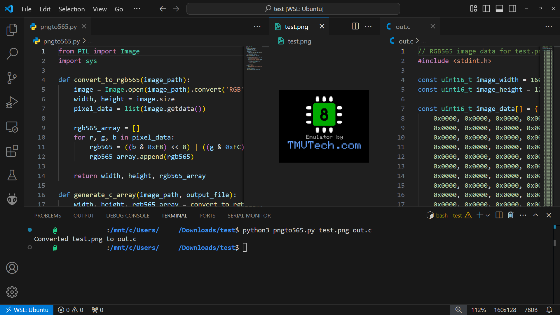
Now we will make a splash screen, an image that appears when the ‘console’ boots up. We start by creating an image with the size of the display, like the one you can see here. Then, using a python script, we will convert it to the format the display expects.

For our python script, we will need the pillow package, we will use it to open the PNG file. You can install it by running:
sudo apt install python3-pillow
# or
pip install pillow
The script below opens an image in the RGB format (for example, a PNG), converts it to RGB565, which uses 5 bits for red and blue and 6 bits for the green channel instead of the usual 8 per channel. Finally, it converts it to a C file, which we can then copy to our project.
from PIL import Image
import sys

def convert_to_rgb565(image_path):
    image = Image.open(image_path).convert('RGB')
    width, height = image.size
    pixel_data = list(image.getdata())

    rgb565_array = []
    for r, g, b in pixel_data:
        rgb565 = ((b & 0xF8) << 8) | ((g & 0xFC) << 3) | (r >> 3)
        rgb565_array.append(rgb565)

    return width, height, rgb565_array

def generate_c_array(image_path, output_file):
    width, height, rgb565_array = convert_to_rgb565(image_path)

    with open(output_file, 'w') as f:
        f.write(f"// RGB565 image data for {image_path}\n")
        f.write(f"#include <stdint.h>\n\n")
        f.write(f"const uint16_t image_width = {width};\n")
        f.write(f"const uint16_t image_height = {height};\n\n")
        f.write("const uint16_t image_data[] = {\n    ")

        for i, value in enumerate(rgb565_array):
            f.write(f"0x{value:04X}, ")
            if (i + 1) % 12 == 0:
                f.write("\n    ")

        f.write("\n};\n")

if __name__ == "__main__":
    if len(sys.argv) != 3:
        print("Usage: python script.py <input.png> <output.c>")
        sys.exit(1)

    input_image = sys.argv[1]
    output_c_file = sys.argv[2]
    generate_c_array(input_image, output_c_file)
    print(f"Converted {input_image} to {output_c_file}")
After saving your script, run it giving it an image with the dimensions of our display (160 by 128) and the name of the output file:
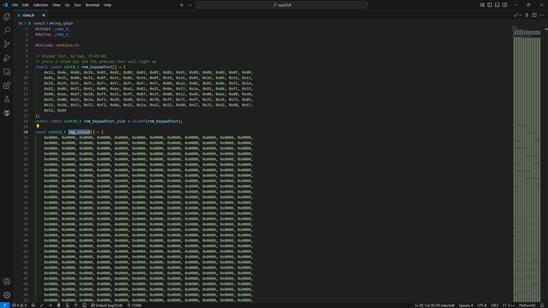
Take the array generated by the script and paste in your ‘roms.h’ file:
The splash function will draw our splash screen and then, 30 times a second, check if any key is pressed, if it is, skip the splash screen, if no key is pressed, the splash screen will stay for 2 seconds:
void Menu::splash()
{
    // Draw splash
    _disp->drawRGBBitmap(0, 0, img_splash, _disp->width(), _disp->height());

    // Splash duration = 2 secs
    const uint16_t hz = 30;
    for (uint8_t i = 0; i < hz * 2; i++)
    {
        // get start time
        uint64_t t0 = _time->getus();
        // update keyboard
        _keys->update();
        // skip splash if key pressed
        if (_keys->anyPressed())
            return;
        // calculate sleep time
        int64_t sleepTime = (1000000 / hz) - (int64_t)(_time->getus() - t0);
        // sleep if needed
        if (sleepTime > 0)
            _time->waitus(sleepTime);
    }
}
In my setup I have a bug where, on cold boots, my screen would not display Bitmaps. To prevent having a black screen for two seconds, we draw the text to the screen and then the Bitmap above it, that way, either we have the text or the whole bitmap showing, but never a blank screen:
void Menu::splash()
{
    const uint16_t hz = 30;

    // Draw text (this is here due to bitmaps not being displayed on cold boots)
    _disp->setTextColor(0xAD55);
    _disp->setTextWrap(false);
    _disp->setCursor(48, 77);
    _disp->print("Emulator by");
    _disp->setTextColor(0xF4CB);
    _disp->setTextSize(2);
    _disp->setCursor(15, 88);
    _disp->print("TMVTech.com");
    _disp->setTextSize(1);
    _disp->setCursor(1, 1);

    // Draw splash
    _disp->drawRGBBitmap(0, 0, img_splash, _disp->width(), _disp->height());

    // Splash duration = 2 secs
    for (uint8_t i = 0; i < hz * 2; i++)
    {
        // get start time
        uint64_t t0 = _time->getus();
        // update keyboard
        _keys->update();
        // skip splash if key pressed
        if (_keys->anyPressed())
            return;
        // calculate sleep time
        int64_t sleepTime = (1000000 / hz) - (int64_t)(_time->getus() - t0);
        // sleep if needed
        if (sleepTime > 0)
            _time->waitus(sleepTime);
    }
}
main.cpp
The main file will include the modules and declare them. On ‘setup’, we initialize the logger and emulator, show the splash screen and then the menu. On ‘loop’, we run one emulator tick and if the return value is positive, wait for that amount of microseconds:
#include <Arduino.h>
#include <SPI.h>

#include "pins.h"
#include "menu.h"
#include "chip8/chip8.h"
#include "modules/display.h"
#include "modules/keyboard.h"
#include "modules/logger.h"
#include "modules/random.h"
#include "modules/sound.h"
#include "modules/time.h"
#include "roms.h"

EspLogger logger;
EspDisplay display(DISP_CS, DISP_DC, DISP_RST);
EspKeyboard keyboard(&logger, GPIO_NUM_26, GPIO_NUM_25, GPIO_NUM_33, GPIO_NUM_32,
                              GPIO_NUM_35, GPIO_NUM_34, GPIO_NUM_39, GPIO_NUM_36 );
EspRandom myrand;
EspSound sound(GPIO_NUM_2, 8, 440, 8);
EspTime tm;

Chip8 emulator(&display, &keyboard, &logger, &myrand, &sound, &tm);
Menu menu(SD_CS, &emulator, &logger, &display, &keyboard, &tm);

void setup()
{
    // Initialize logger
    if (!logger.init())
    {
        vTaskDelay(5000 / portTICK_PERIOD_MS);
        ESP.restart();
    }

    // Load default ROM and init emulator
    if (!emulator.init(rom_KeypadTest, rom_KeypadTest_size))
    {
        logger.error("Can't initialize the emulator! Rebooting in 5 secs...");
        vTaskDelay(5000 / portTICK_PERIOD_MS);
        ESP.restart();
    }
    logger.info("Ready!");

    // Show splash screen
    menu.splash();
    // Show menu
    menu.show();
}

void loop()
{
    int64_t st = emulator.tick();
    if (st > 0)
        tm.waitus(st);
}
After flashing your code, you should now have a simple, but functional, menu to select your ROMs:
The next step in our project will be to build the console. In the next chapter you will be able to find the STL files for the case, but you will also need some extra materials, like:
- 1x Type C port breakout board
- 1x 5 by 7 Protoboard
- M2 nuts and bolts of various lengths (largest used is 3 cm)
- Some kind of non-conductive tape
To print the case, I used black PLA and the Bambu Lab P1P printer. For the front panel, I flipped it to avoid using supports and with the walls I tried both with and without supports, and it printed fine either way, but I am sure that with an older printer it would probably need them. The back panel was printed as is. Some slicers might load the models with a very small size, if yours does that, scale the model 10 times in every axis.
You can get the models by clicking the images below:
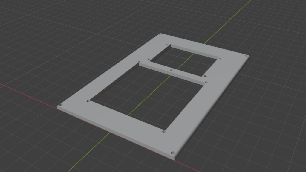
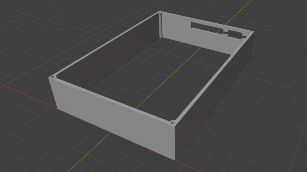
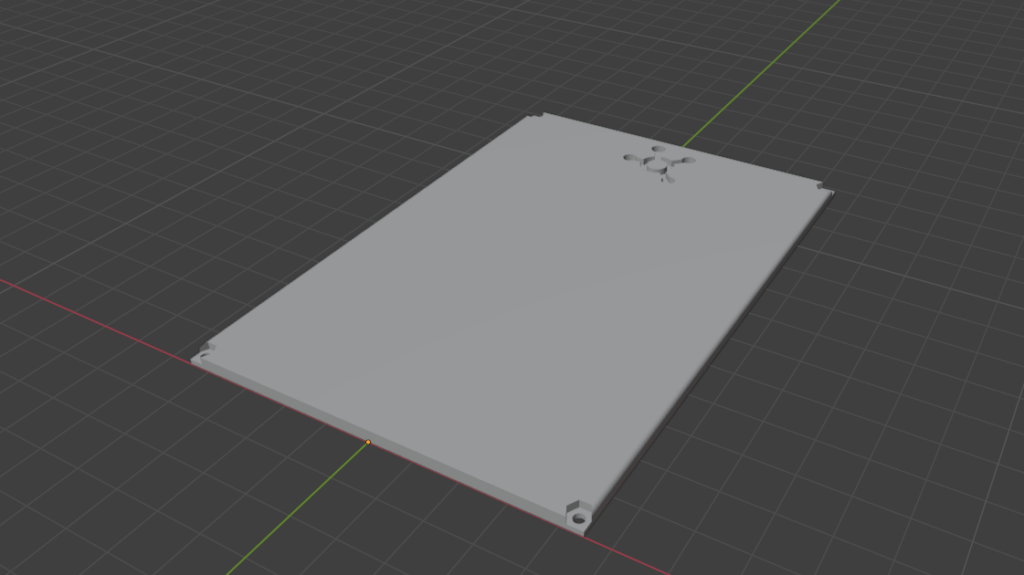
Now we need to use a protoboard to make the core of our console. We will use some headers to place the Esp32 on (column 4 and 14), mine has 15 pins on each side. Then we will also need some pins. On column 3, we will need to add 5 pins, from K to O, on column 15 we will add pins at A, F, G, H, K, L, N and O, and on 16 we add pins on A, G, N and O. Finally, on column 17 we add pins to 3.3V and ground (N and O). Also on the back, add 10K resistors between V6 to V9 and N, which is the ground pin on the Esp32.
On the front, the side where we will place the keypad on, add some pins from X13 to X6. Then, starting from the left, solder a wire between V13 and I5, then V12 to H5, V11 to G5, V10 to F5, U9 to E5, U8 to D5, U7 to C5 and U6 to B5. Finally, add the traces (black lines) like on the image below:
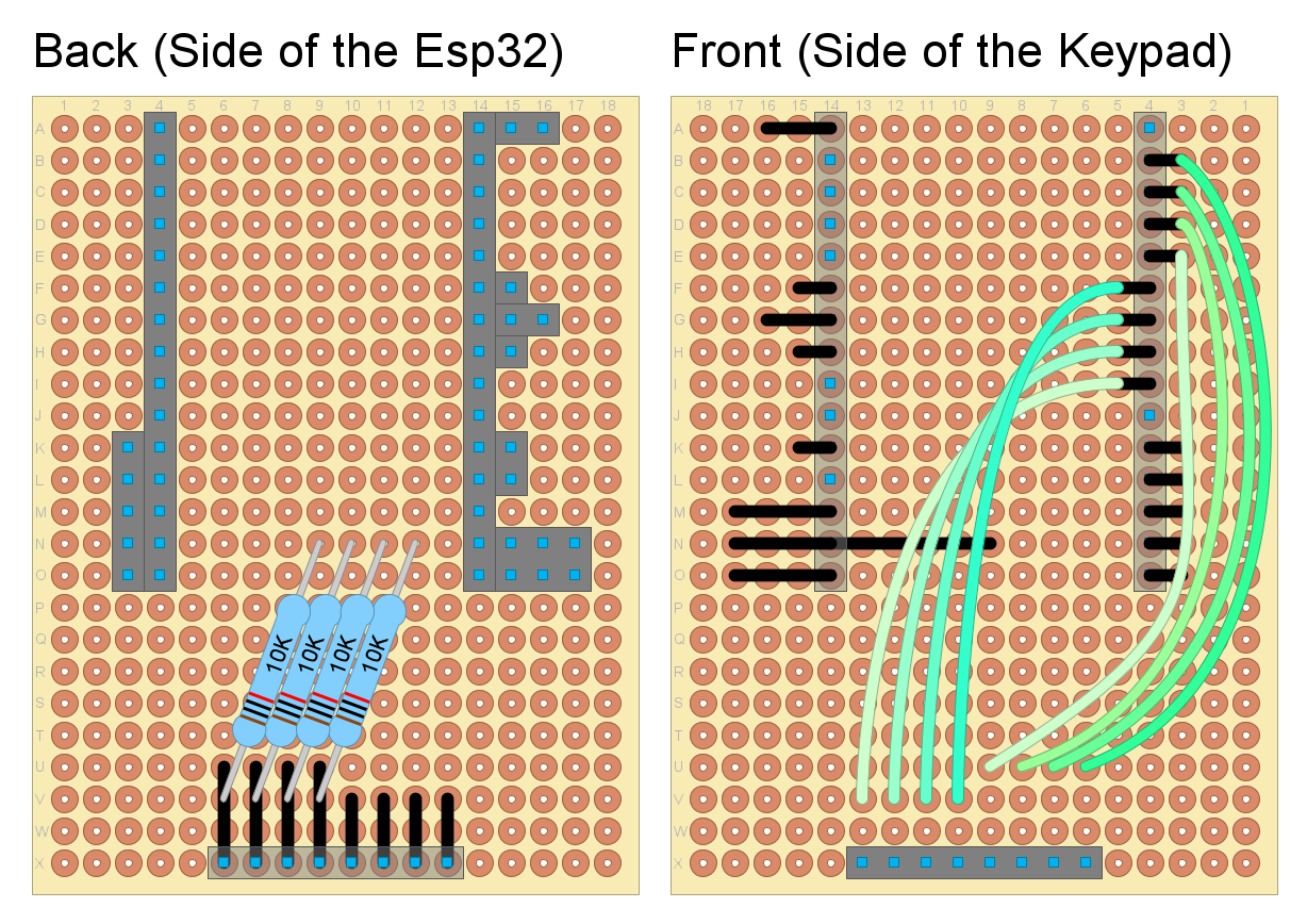
After soldering everything, you should have something similar to the image below. Now, I would encourage you to spend some time with the multimeter in continuity mode, testing every pin and connection making sure everything is wired correctly.
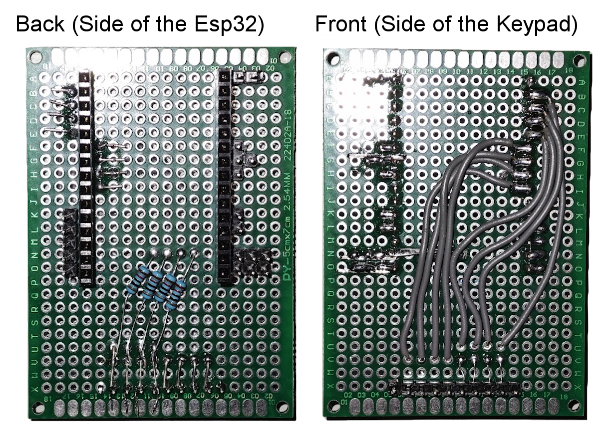
Once you are done checking the connections, we will need to solder the keypad, but before that, let’s use our yellow tape to cover everything that might cause a short. It is better to use too many tape than not enough!
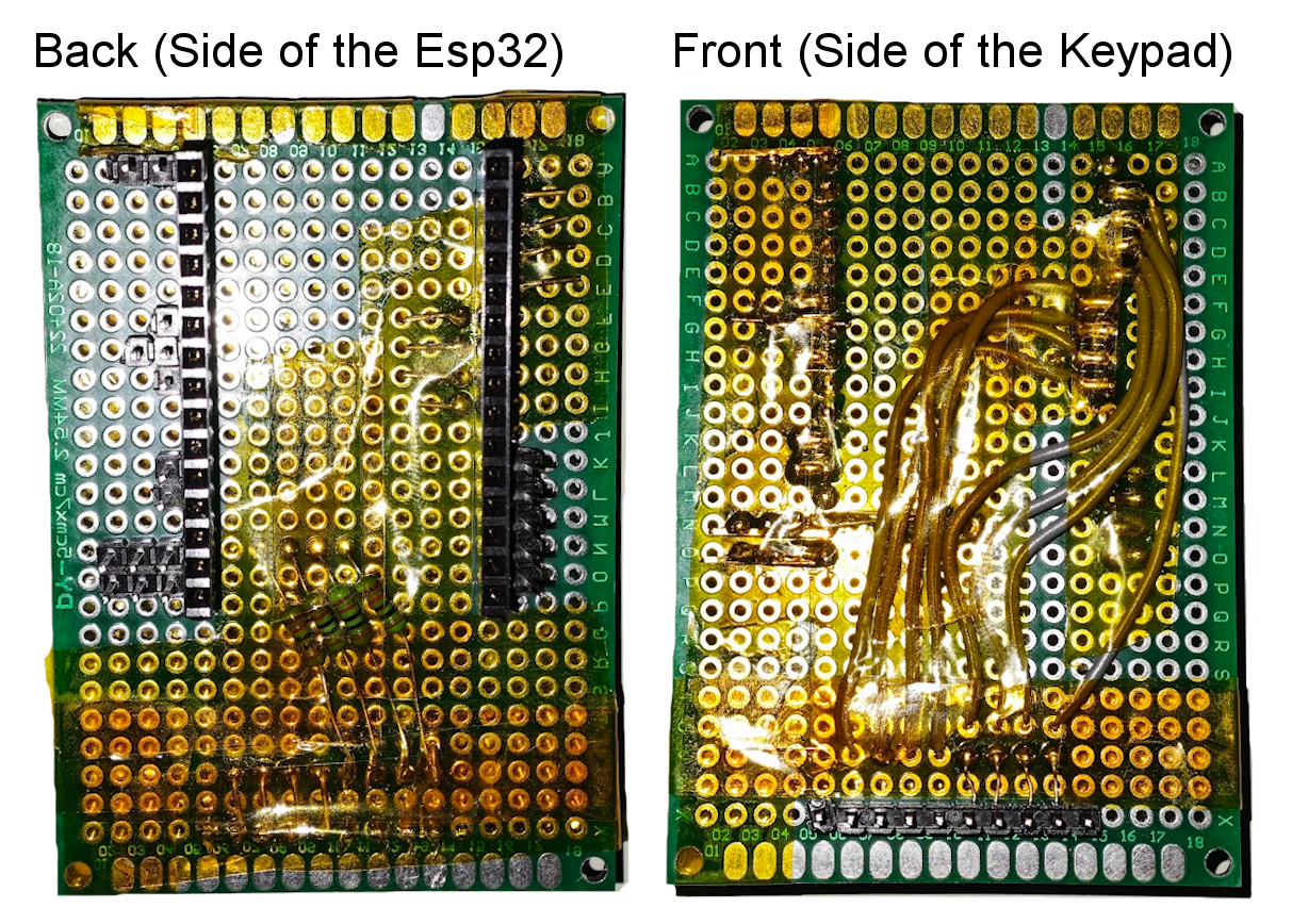
Add the keyboard and plug in the Esp32. I encourage you to take some time again and test all the components. Plug everything in and test the code. Try to play a game, test all the buttons on the keyboard, test everything that you can.
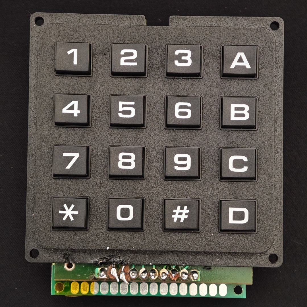
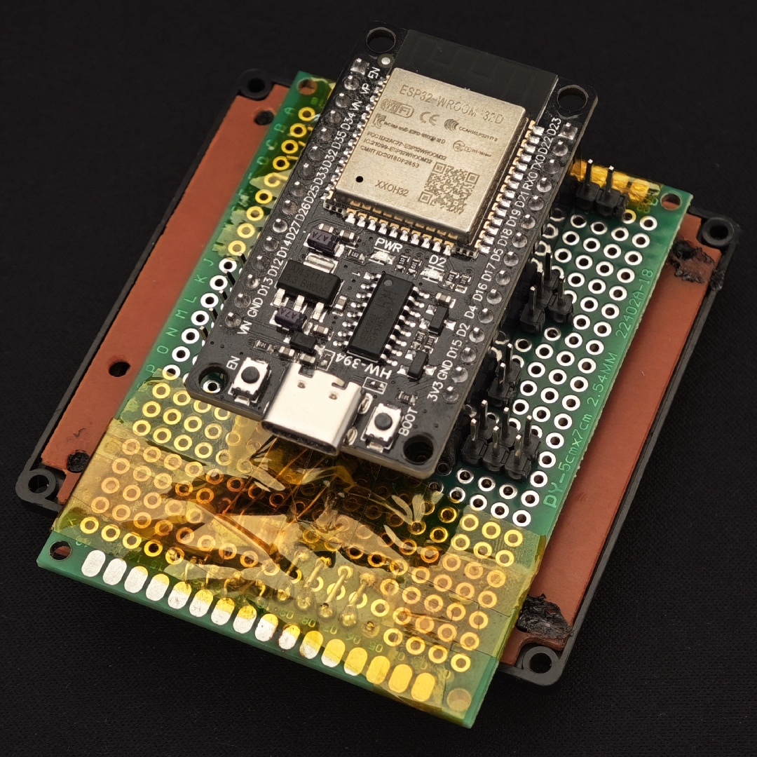
If everything is working correctly, the next step is to assemble everything! Take your display and screw it into the front plate. Make sure the display’s pins are on the same side as the cut on the front plate. On the image below you can see two highlighted screw holes, these will need longer screws, something between 1.5 and 2 cm should be fine.
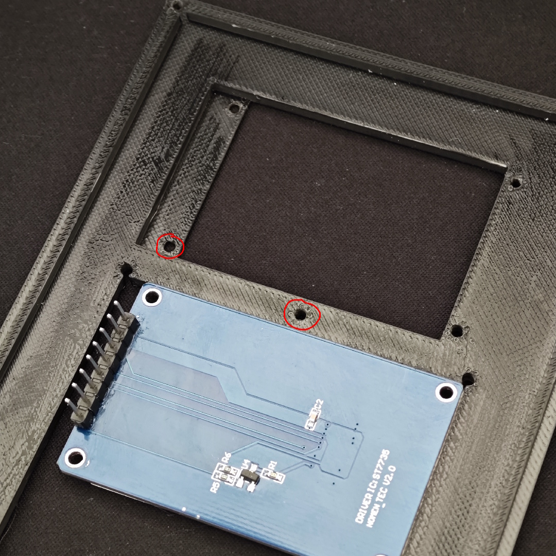
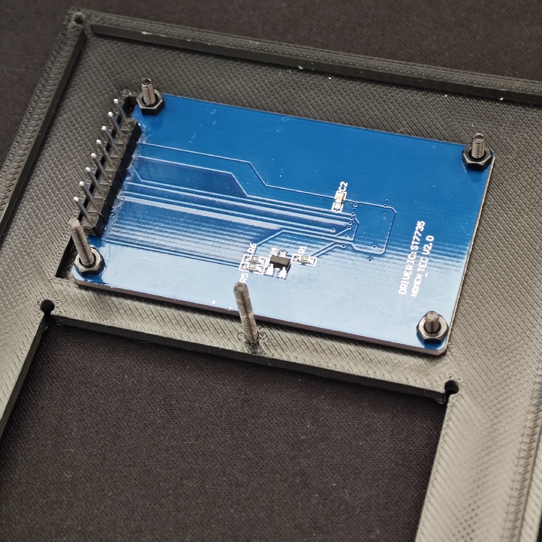
Now we will screw in the keyboard, on the top right, use a longer screw so that we can later place the buzzer on it. Looking back at the display’s longer screws, add some nuts to them so that we can then place the SD card reader above it.
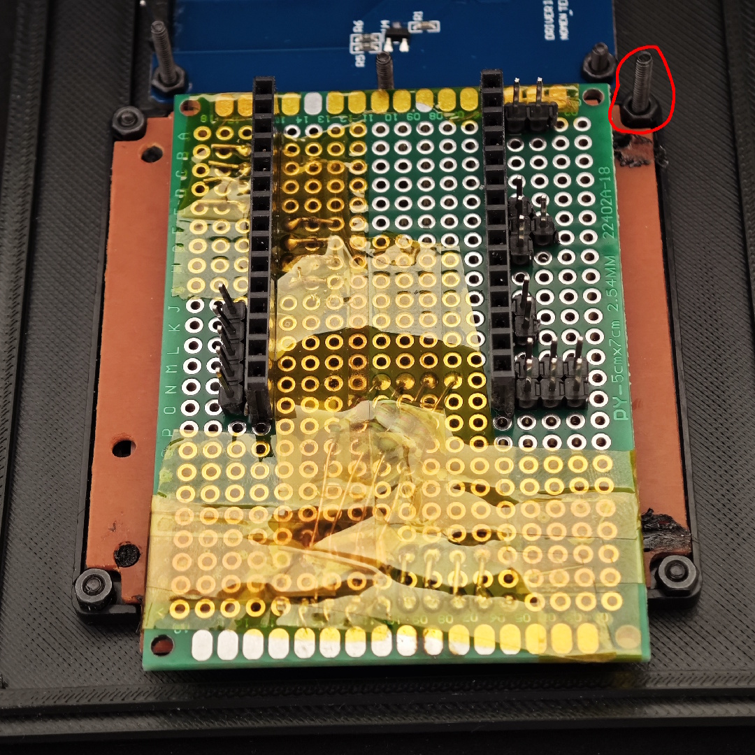
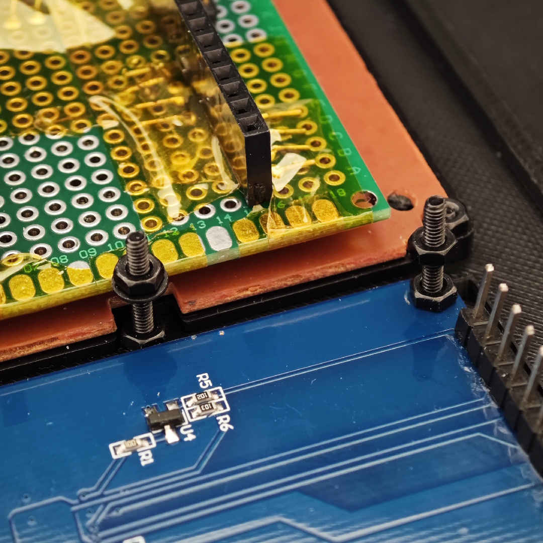
Screw in the SD Card reader and the buzzer. Make sure the SD Card does not wobble too much and that the buzzer’s pins are pointed to the top:
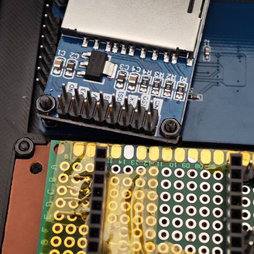
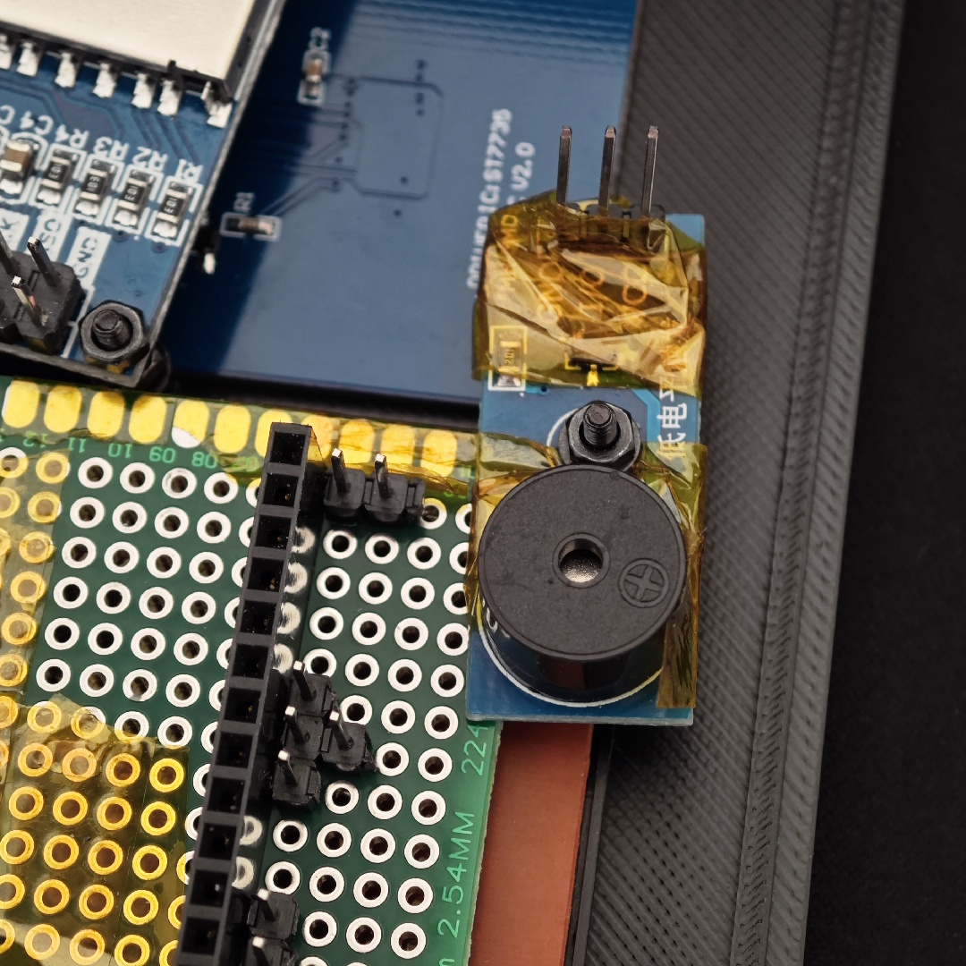
Let’s now wire the buzzer. The buzzer uses 3 wires, 3.3V, ground and signal. Plug the signal wire to D2.
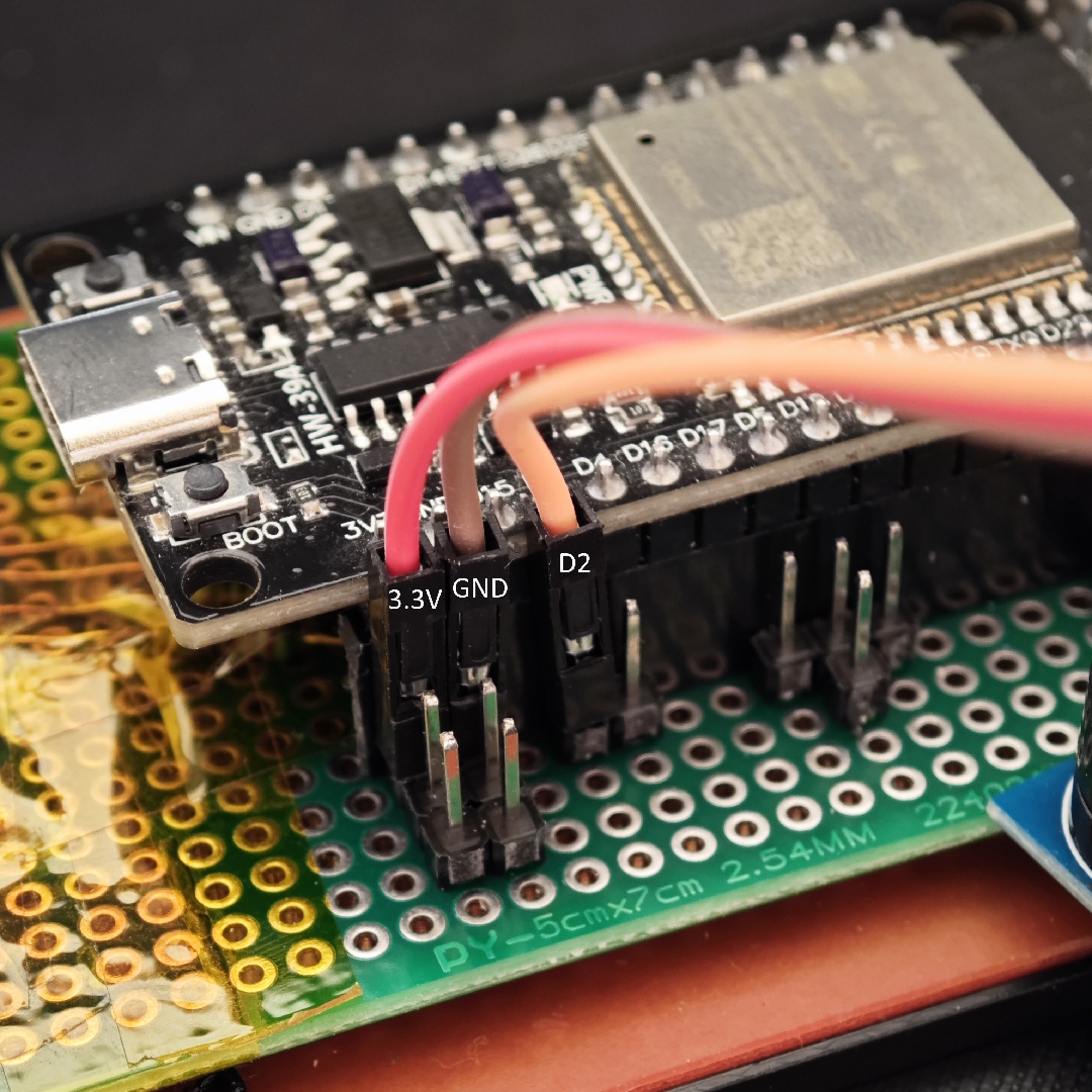
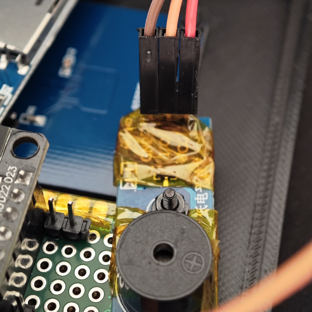
Next is the display, plug in the SPI pins, CS goes to D4, power and on the other side, RST is D14 and DC D13:
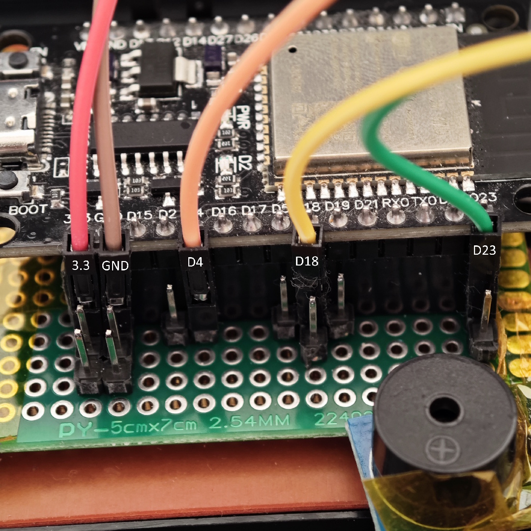
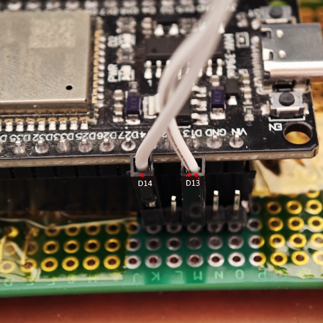
Plug the wires into the display, leave the bottom pin unplugged (that is the backlight), then give the Esp power and test the screen, buzzer, and the keyboard. If your display works, you will get an error saying you don’t have an SD card, hold D to open up the keyboard tester.
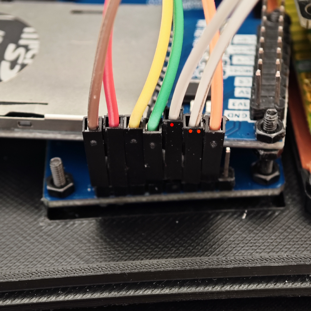
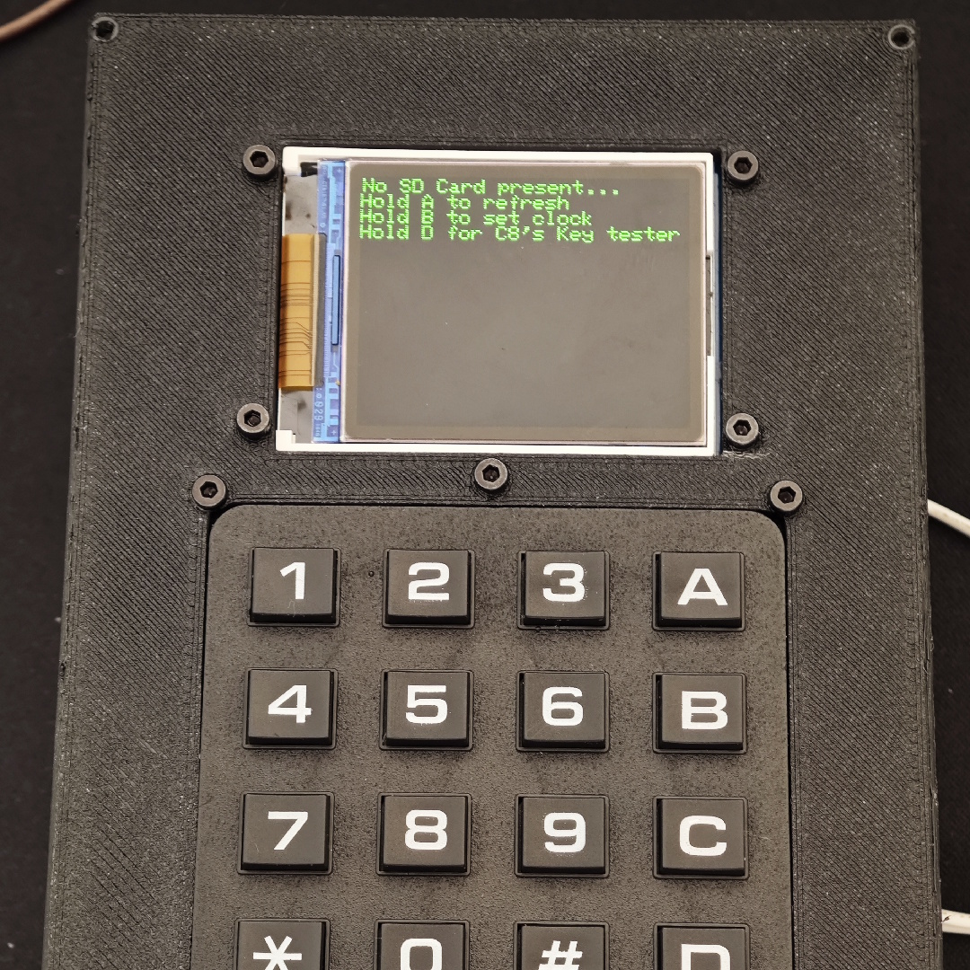
Finally, we focus on the SD Card. Plug the SPI wires to the Esp32 (MOSI to D23, MISO to D19, SCK to D18, CS to D5) and then power:
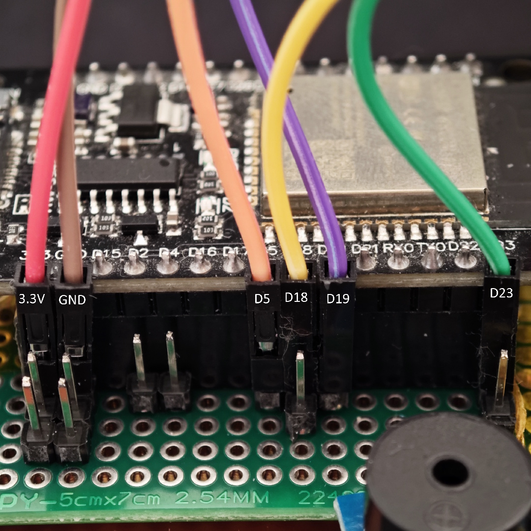
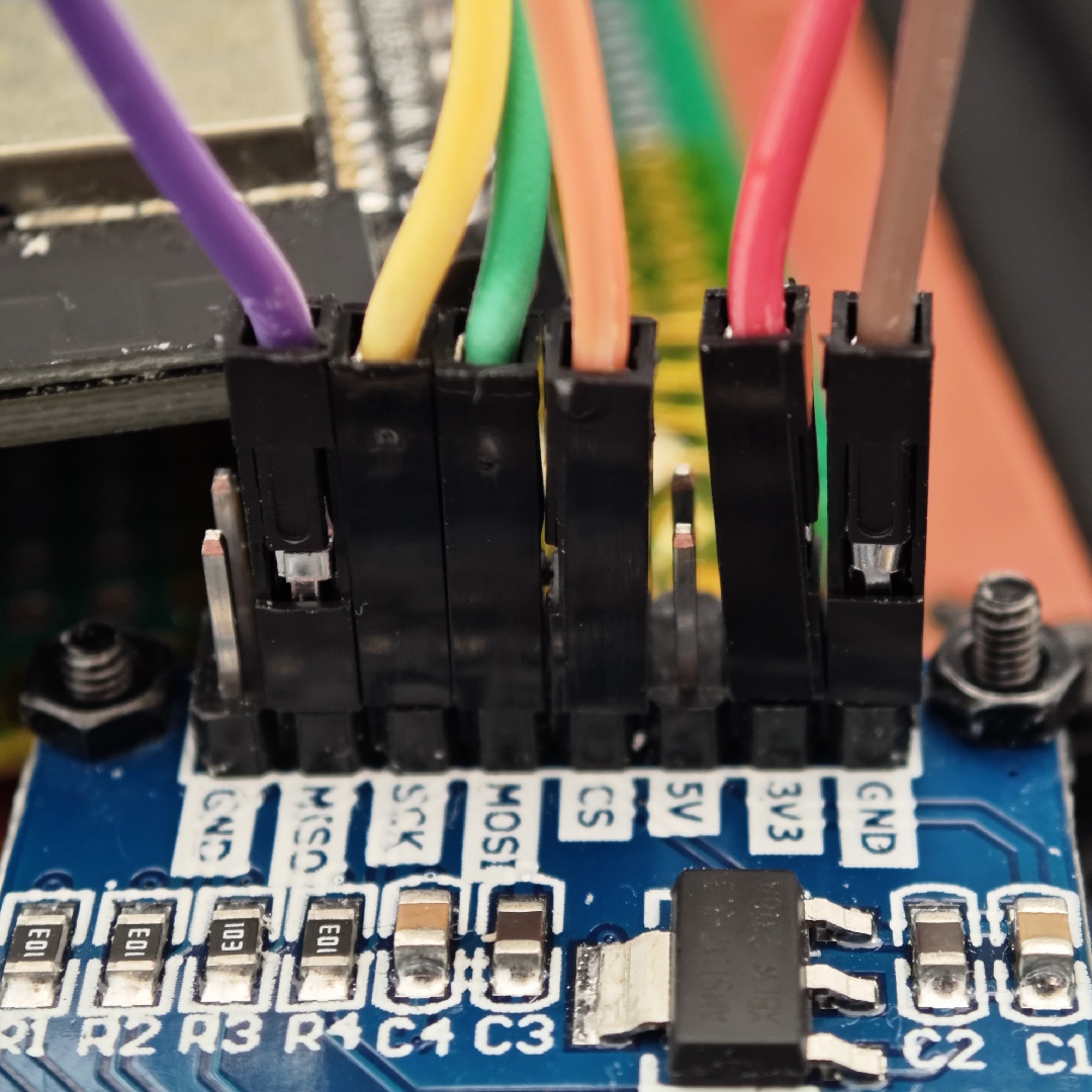
You should, again, test the components and after that, we focus on the walls. On the walls, we will add the Type C port that will supply power to our console. Solder some pins to the bottom side of the port and then plug 5V to VIN on the Esp32 and then ground to the left ground of the Esp32.
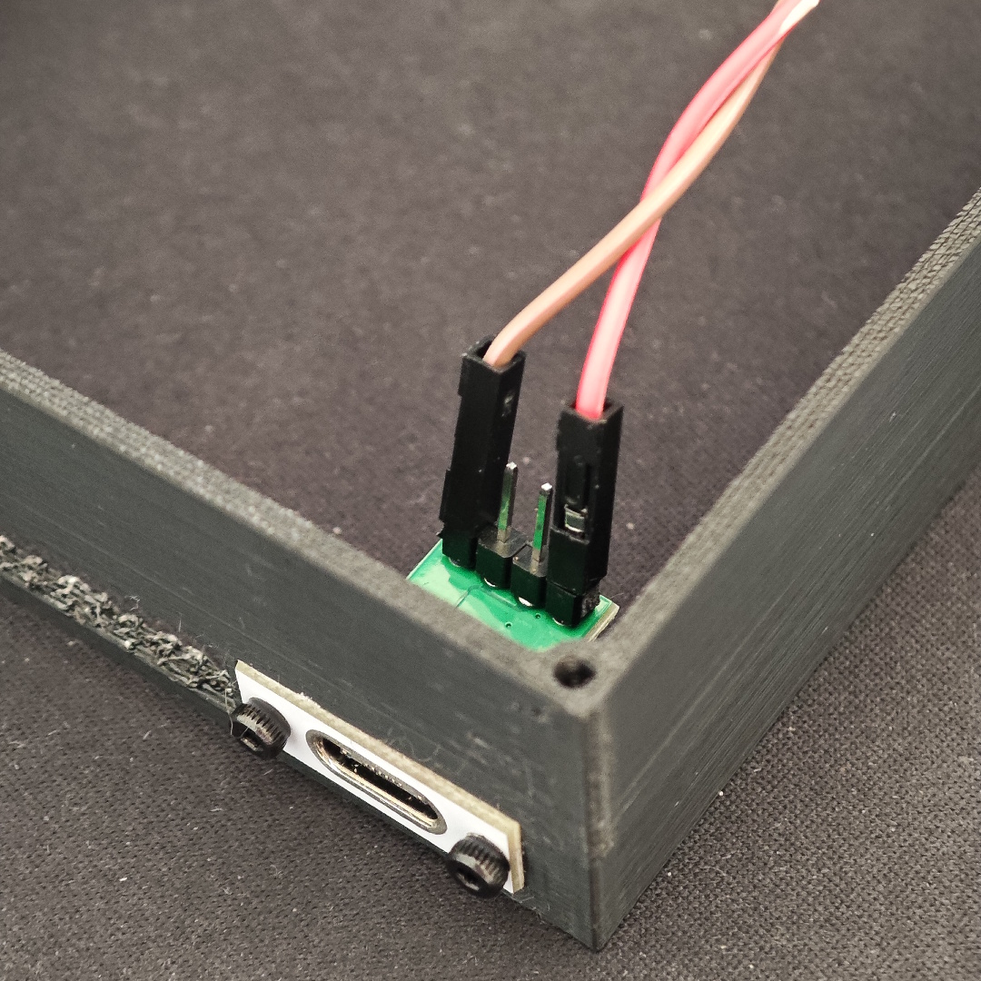
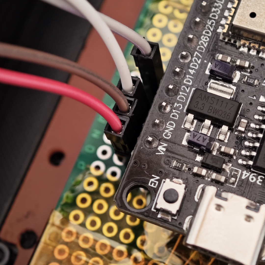
Screw in the walls, do some cable management (if possible, better than mine) so that everything fits correctly, add some nuts to the backplate, and screw it on.
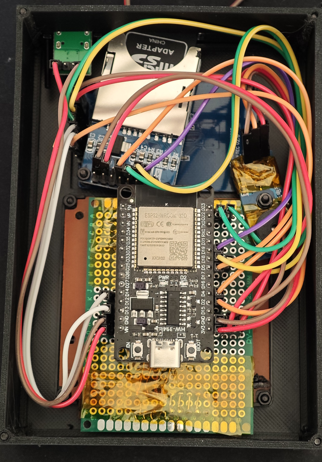
And your console is done! Try plugging it in now, add an SD Card with lots of games, and you are ready to game!
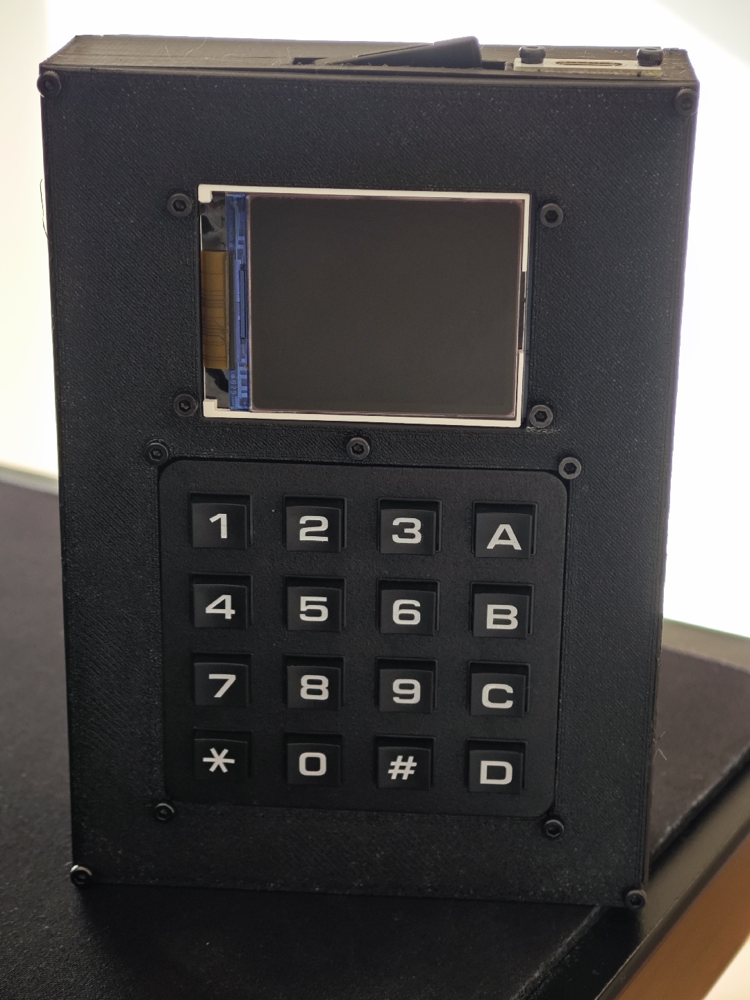
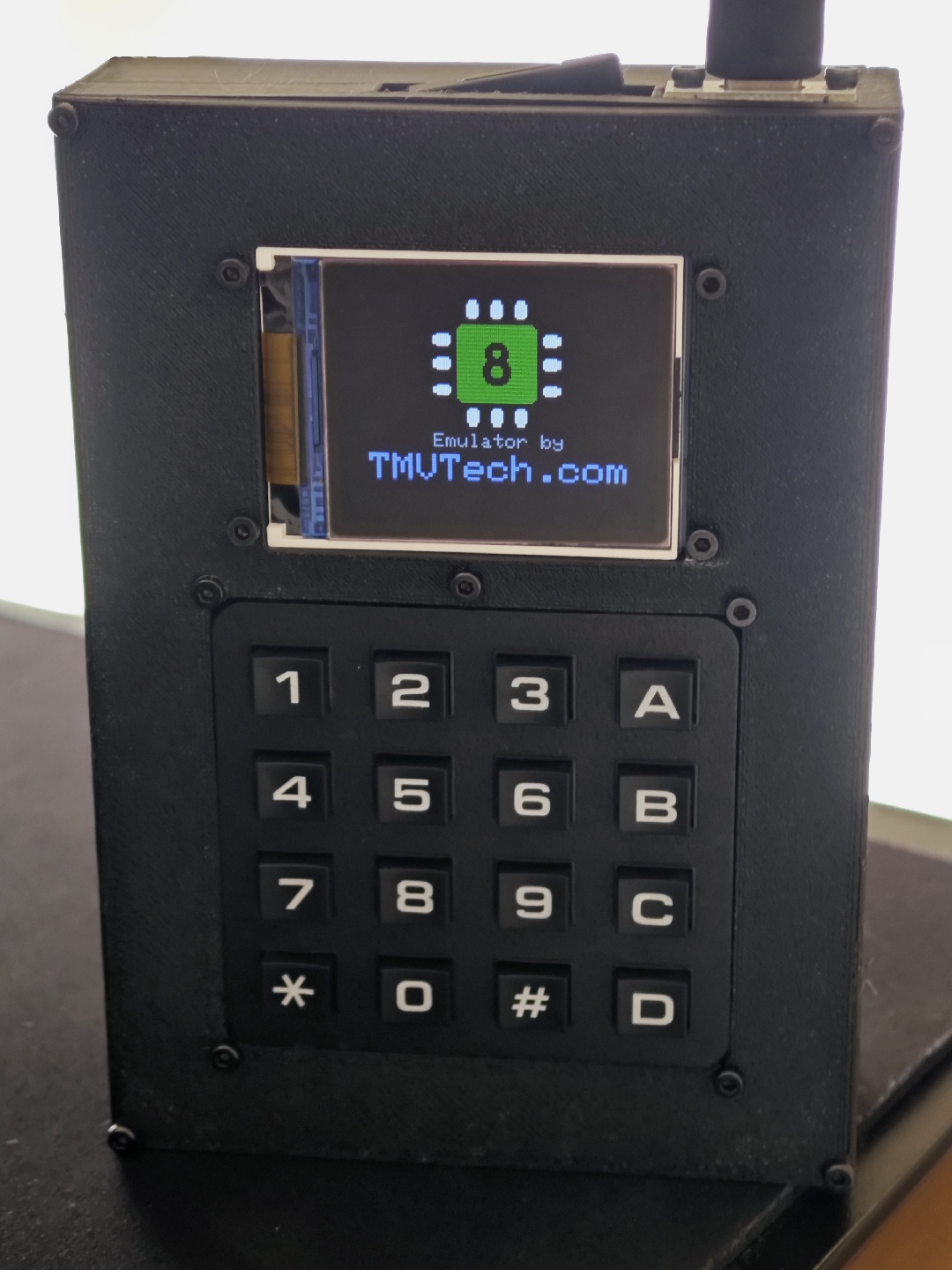
Now that you have a console working, if you want to get some games, you can check our GitHub repo for the Chip8 emulator on Ubuntu. Below, you can find a small video exploring the menus and trying to play games on the emulator:
And that’s all for this article. Thanks for reading, and stay tuned for more tech insights and tutorials. Until next time, and keep exploring the world of tech!