
0 - Introduction
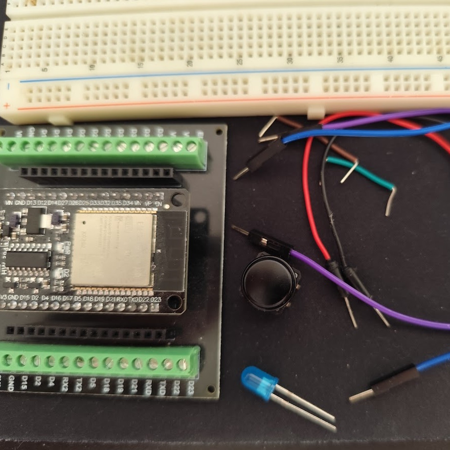
This small project will show you how to use an Esp32 to read the state of a button and output it to a LED, you should also be able to recreate this project with little to no changes in a arduino. For this, you will need:
- 1x Esp32
- 1x Button
- 1x Led
- 1x Breadboard
- Atleast 6 small cables
Before you start, make sure you have Platform IO installed and with the Espressif 32 platform, you can learn how to install them in this article.
1 - Code
Start by creating a new project and deleting the example function. In this project we will only need the ‘Arduino’ include to be able to read, write and set pin modes. Let’s start with the setup, in here i chose pins 22 and 23 because they are free pins on the ‘top-left’ of my esp, 22 will be the input from the button and 23 will be the output to the LED:
#include <Arduino.h>

void setup()
{
    // PULLDOWN is low when not clicked
    pinMode(GPIO_NUM_22, INPUT_PULLDOWN);
    // Pin that goes to the LED
    pinMode(GPIO_NUM_23, OUTPUT);
}
In the loop we do three simple steps, read the state of the button pin, write the state to the led pin and finally wait a little before repeating:
void loop()
{
    // Read state of the button
    int state = digitalRead(GPIO_NUM_22);
    // Change state of the led
    digitalWrite(GPIO_NUM_23, state);
    // Sleep 100ms (loop runs at 10Hz)
    vTaskDelay(100 / portTICK_PERIOD_MS);
}
Now, we need to build the circuit, you can do that by following this wokwi diagram, be carefull that the 3.3v pin in Wokwi and your esp’s 3.3v pin can be in different places!
If you also want to test the code in Wokwi, you can copy the following ‘diagram.json’.
In Wokwi after pasting both the code and the ‘diagram.json’, you should be able to run the simulation and press the button to see the led light up.
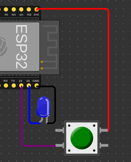
{
"version": 1,
"author": "TMVTech",
"editor": "wokwi",
"parts": [
{
"type": "board-esp32-devkit-c-v4",
"id": "esp",
"top": 0,
"left": 0,
"rotate": 90,
"attrs": {}
},
{
"type": "wokwi-pushbutton",
"id": "btn1",
"top": 198.2,
"left": 153.6,
"attrs": { "color": "green" }
},
{
"type": "wokwi-led",
"id": "led1",
"top": 159.6,
"left": 119.4,
"attrs": { "color": "blue", "flip": "1" }
}
],
"connections": [
[ "esp:23", "led1:A", "blue", [ "v0" ] ],
[ "led1:C", "esp:GND.2", "black", [ "v0", "h9.2", "v-48" ] ],
[ "esp:3V3", "btn1:1.r", "red", [ "v-1.51", "h90.1" ] ],
[ "esp:22", "btn1:2.l", "purple", [ "v0" ] ]
],
"dependencies": {}
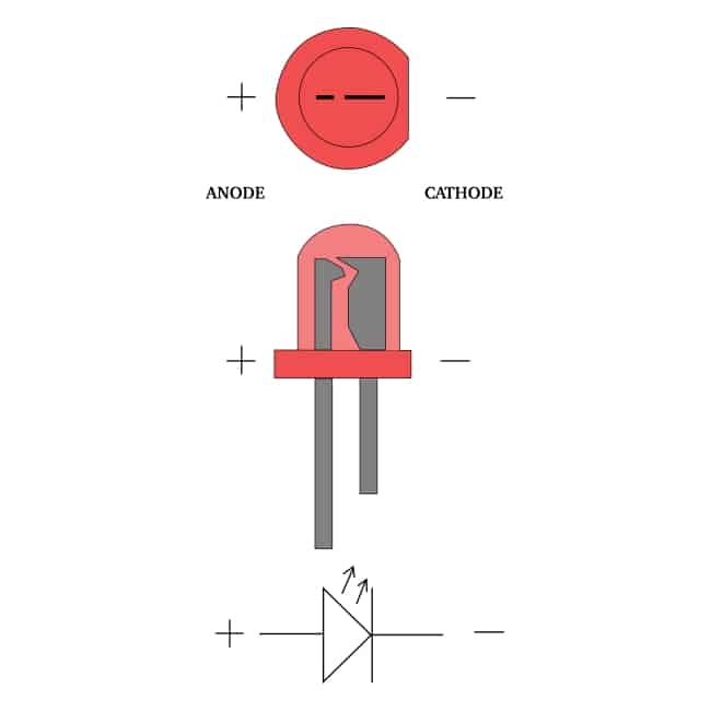
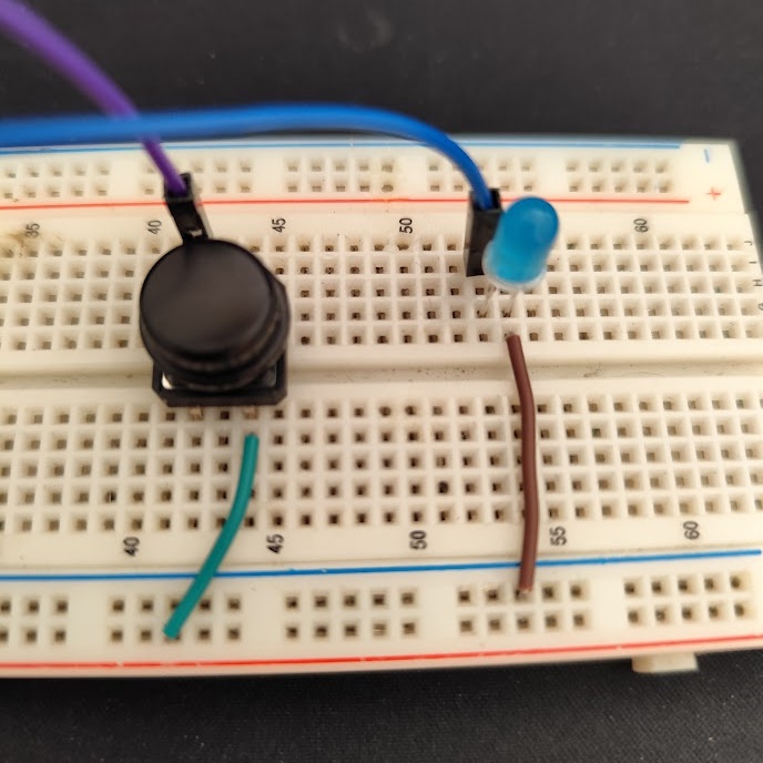
}Before trying to make your own circuit let’s talk about the leds and the buttons. Leds with only one color, 99% of the time, have only two legs, with one being bigger than the other, the bigger one is the ‘+’ or the 3.3v and, the smaller one, is the ‘-‘ or the ground.
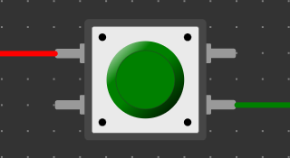
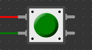
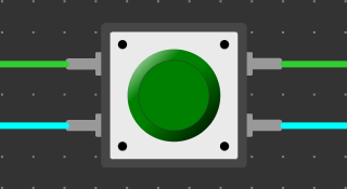
When it comes to buttons, the most common are the 4 leg button types, in those, the pins are connected in pairs and, when you press the button, all 4 of them connect. To wire a button to the esp you have two options, either you wire both of them on the same side, or one on the top left and the other on the bottom right, or one on the bottom left and the other on the top right. You can see in these images how to wire them:
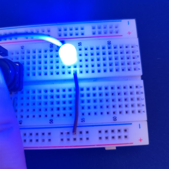
And that’s it, if you recreate the circuit in your breadboard, you should be able to press the button and see the LED light up!
We can also slightly change our code to make the button turn the led on when we press it once and turn it off when we press it again, to do that you need two ‘int’ variables, one that houses the led state and another that saves the last state of the button.
We then need to make a if clause that checks if the button is now pressed and, if on the last loop, it was not, we can do that by comparing the current button state with the last one. After that, inside the if statement, we need to change the led state by inverting it and then write it to the pin (turning the led on or off).
Lastly, we need to save the old button state and we add a very small delay, so that the esp does not work too much without it being needed. With the 10 millisecond delay, the esp does a check 100 times per second, that is more than enough for our little project.
int lastbtnstate = LOW;
int ledstate = LOW;

void loop()
{
    // Read state of the button
    int btnstate = digitalRead(GPIO_NUM_22);
    // When button is clicked
    if (lastbtnstate != btnstate && btnstate == HIGH)
    {
        // Change state of the led
        ledstate = !ledstate;
        digitalWrite(GPIO_NUM_23, ledstate);
    }
    // Save last button state
    lastbtnstate = btnstate;
    // Sleep 10ms (loop runs at 100Hz)
    delay(10);
}
And that’ it, this article was a very simple one just to teach people that are starting their journey in the world of microcontrollers, how to both, read a button, and output to a led, we hope you understood how it works and also that you learnt what is Wokwi and how to use it to simulate your projects before building them.
Thanks for reading and stay tuned for more tech insights and tutorials. Until next time, and keep exploring the world of tech!